Sentinel-1 is the European Radar Observatory, representing the first new space component of the GMES (Global Monitoring for Environment and Security) satellite family, designed and developed by ESA and funded by the EC (European Commission). The Kopernikus missions (Sentinel-1, -2, and -3) represent the EU contribution to GEOSS (Global Earth Observation System of Systems).
Sentinel-1 is the European Radar Observatory, representing the first new space component of the GMES (Global Monitoring for Environment and Security) satellite family, designed and developed by ESA and funded by the EC (European Commission). The Kopernikus missions (Sentinel-1, -2, and -3) represent the EU contribution to GEOSS (Global Earth Observation System of Systems).
|
Copernicus is the new name of the European Commission's Earth Observation Programme, previously known as GMES (Global Monitoring for Environment and Security). The new name was announced on December 11, 2012, by EC (European Commission) Vice-President Antonio Tajani during the Competitiveness Council. In the words of Antonio Tajani: “By changing the name from GMES to Copernicus, we are paying homage to a great European scientist and observer: Nicolaus Copernicus (1473-1543). As he was the catalyst in the 16th century to better understand our world, so the European Earth Observation Programme gives us a thorough understanding of our changing planet, enabling concrete actions to improve the quality of life of the citizens. Copernicus has now reached maturity as a programme and all its services will enter soon into the operational phase. Thanks to greater data availability user take-up will increase, thus contributing to that growth that we so dearly need today.” |
Table 1: Copernicus is the new name of the former GMES program 1)
The overall objective of the Sentinel-1 mission is to provide continuity of C-band SAR operational applications and services in Europe. Special emphasis is placed on services identified in ESA's GSE (GMES Service Element) program. Additional inputs come from on-going GMES projects funded by ESA, the EU, and ESA/EU member states. The Sentinel-1 mission is expected to enable the development of new applications and meet the evolving needs of GMES, such as in the area of climate change and associated monitoring. 2) 3) 4)
The Sentinel-1 mission represents a completely new approach to SAR mission design by ESA in direct response to the operational needs for SAR data expressed under the EU-ESA GMES (Global Monitoring for Environment and Security) program. The mission ensures continuity of C-band SAR data to applications and builds on ESA's heritage and experience with the ERS and Envisat SAR instruments, notably in maintaining key instrument characteristics such as stability and accurate well-calibrated data products.
The key mission parameters are revisit time, coverage, timeliness combined with frequency band, polarization, resolution and other image quality parameters. Short revisit time demands for an appropriate orbit selection and large swath widths.
The baseline mission concept under development is a two-satellite constellation, with four nominal operational modes on each spacecraft designed for maximum compliance with user requirements. 5) 6) 7) 8) 9) 10)
• Orbit: Sun-synchronous near-polar orbit, repeat cycle of 12 days, cycle length of 175 days
• Operational modes:
- Stripmap mode (SM): 80 km swath, 5 m x 5 m resolution, single-look
- Interferometric Wide Swath mode (IWS): 240 km swath, 5 m x 20 m resolution, single-look
- Extra Wide Swath mode (EWS): 400 km swath, single-look
- Interferometric Wide Swath mode (IWS): 240 km swath, 25 m x 80 m resolution, 3-looks
- Wave mode (WM): 20 km x 20 km, 20 m x 5 m resolution, single-look
• Polarization: Dual polarization for all modes VV+VH or HH+HV
• Operations:
- Consistent, reliable and conflict free mission operations
- Near real-time delivery of data within 3 hours (worst case) with 1 hour as goal
- Data delivery from archive within 24 hours
• Sensitivity: NESZ (Noise Equivalent Sigma Zero), σo = -25 dB
• Radiometry:
- Stability = 0.5 dB
- Accuracy = 1.0 dB
• Ambiguity ratio: DTAR (Distributed Target Ambiguity Ratio) = -25 dB
In April 2007, ESA selected TAS-I (Thales Alenia Space Italia) as prime contractor for the Sentinel-1 spacecraft (overall satellite design & integration at system and subsystem level, including the design of the SAR antenna's transmit/receive modules). ESA awarded the contract to TAS-I on June 18, 2007 at the Paris International Air Show. EADS Astrium GmbH of Friedrichshafen, was in turn awarded a contract by TAS-I to build the radar imaging payload for Sentinel-1, including the central radar electronics subsystem developed by Astrium UK. The objective of Sentinel-1 is to assure C-band SAR data continuity for the user community currently provided by Envisat and ERS-2. 11)
Three priorities (fast-track services) for the mission have been identified by user consultation working groups of the European Union: Marine Core Services, Land Monitoring and Emergency Services. These cover applications such as: 12)
• Monitoring sea ice zones and the arctic environment
• Surveillance of marine environment
• Monitoring land surface motion risks
• Mapping of land surfaces: forest, water and soil, agriculture
• Mapping in support of humanitarian aid in crisis situations.
Unlike its more experimental predecessors ERS-1, ERS-2 and Envisat that supply data on a best effort basis, operational satellites like Sentinel-1 are required to satisfy user requirements and to supply information in a reliable fashion with the data provider accepting legal responsibility for the delivery of information.
In March 2010, ESA and TAS-I signed a contract to build the second Sentinel-1 (Sentinel-1B) and Sentinel-3 (Sentinel-3B) satellites, marking another significant step in the Copernicus program. 13)
As part of the Copernicus space component, the Sentinel-1 (S1) mission is implemented through a constellation of two satellites (A and B units) each carrying an imaging C-band SAR instrument (5.405 GHz) providing data continuity of ERS and Envisat SAR types of mission. Each Sentinel-1 satellite is designed for an operations lifetime of 7 years with consumables for 12 years. The S-1 satellites will fly in a near polar, sun-synchronized (dawn-dusk) orbit at 693 km altitude. 14)
The Sentinel-1 mission, including both S-1A and S-1B satellites, is specifically designed to acquire systematically and provide routinely data and information products to Copernicus Ocean, Land and Emergency as well as to national user services. These services focus on operational applications such as the observation of the marine environment, including oil spill detection and Arctic/Antarctic sea-ice monitoring, the surveillance of maritime transport zones (e.g. European and North Atlantic zones), as well as the mapping of land surfaces including vegetation cover (e.g. forest), and mapping in support of crisis situations such as natural disasters (e.g. flooding and earthquakes) and humanitarian aid.
In addition, the 12-day repeat orbit cycle of each Sentinel-1 satellite along with small orbital baselines will enable SAR interferometry (InSAR) coherent change detection applications such as the monitoring of surface deformations (e.g. subsidence due to permafrost melt) and cryosphere dynamics (e.g. glacier flow).

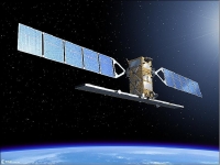
Figure 1: Artist's view of the deployed Sentinel-1 spacecraft (image credit: ESA, TAS-I)
Spacecraft:
The spacecraft is based on the PRIMA (Piattaforma Italiana Multi Applicativa) bus of TAS-I, of COSMO-SkyMed and RADARSAT-2 heritage, with a mission-specific payload module. Attitude stabilization: 3-axis, attitude accuracy = 0.01º (each axis), orbital knowledge = 10 m (each axis, 3σ using GPS). 15) 16)
The spacecraft structure provides the accommodation for all platform and payload units. A box type structure has been adopted using external aluminum sandwich material, with a central structure in CFRP (Carbon Fiber Reinforced Plastic). A modular approach has been taken whereby the payload is mounted to a dedicated part of the structure, allowing separate integration & test of the payload before integration to the main part of the structure carrying the platform units. This has many advantages for the overall AIT (Assembly, Integration and Test) process. 17)

Figure 2: 3D exploded view of the Sentinel-1 platform (image credit: TAS-I)
TCS (Thermal Control Subsystem): The TCS provides control of the thermal characteristics and environment of the Satellite units throughout all phases of the mission. In general the TCS is passive, with the control provided by means of standard techniques such as heat pipes, radiators and MLI (Multi-Layered Insulation). Survival heaters are provided to prevent units becoming too cold during non-operative phases.
EPS (Electric Power Subsystem): The EPS uses two solar array wings for power generation. Each wing consists of 5 sandwich panels using GaAs triple junction solar cells. The average onboard power is 4.8 kW (EOL), the Li-ion battery has a capacity of 324 Ah. The PCDU (Power Control and Distribution Unit) is designed to provide adequate grounding, bonding & protection for the overall electrical system (e.g. by use of fuses) and must also be integrated into the satellite FDIR concept to ensure that adequate power resources and management are available in the event of on-board failures. Li-Ion battery technology has been selected for the batteries in view of the large benefits offered in terms of mass and energy efficiency.
The spacecraft dimensions in stowed configuration are: 3.4m x 1.3 m x 1.3 m. The Sentinel-1 spacecraft has a launch mass of ~2,300 kg, the design life is 7.25 years (consumables for up to 12 years). 18) 19)
Since the B2 Phase of Sentinel-1, a commonality approach with Sentinel-2 and Sentinel-3 was introduced and deeply investigated, to optimize and minimize as much as possible new developments, HW procurement and operations costs. Besides the differences among payload instruments and their relative required performances, each of these three satellites have its own orbital parameters, as well its own specific requirements. 20) 21)
|
Parameter |
Sentinel-1 |
Sentinel-2 |
Sentinel-3 |
|
First launch |
2014 |
2014 |
2015 |
|
Orbit type |
SSO (Sun-synchronous Orbit) 12 day repeat cycle LTAN = 18:00 hours |
SSO 10 day repeat cycle LTDN = 10:30 hours |
SSO 27 day repeat cycle LTDN = 10:00 hours |
|
Orbital altitude |
693 km |
786 km |
800 km |
|
Sensor complement |
C-SAR (C-band Synthetic Aperture Radar) |
MSI (Multi Spectral Instrument) |
SRAL (Sentinel-3 Radar Altimeter) MWR (MicroWave Radiometer) OLCI (Ocean and Land Color Instrument) SLSTR (Sea and Land Surface Temperature Radiometer) |
|
Spacecraft mass Spacecraft size Spacecraft power |
2300 kg 3.4 m x 1.3 m x 1.3 m 4.8 kW (EOL) |
1100 kg 3.0 m x 1.7 m x 2.2 m 1.7 kW (EOL) |
1250 kg 3.9 m x 2.2 m x 2.2 m 2.05 kW (EOL) |
|
Downlink X-band data rate |
520 Mbit/s |
520 Mbit/s |
520 Mbit/s |
|
TT&C S-band |
64 kbit/s uplink 128 kbit/s or 2 Mbit/s downlink |
64 kbit/s uplink 128 kbit/s or 2 Mbit/s downlink |
64 kbit/s uplink 128 kbit/s or 2 Mbit/s downlink |
|
Science data storage |
1.4 Tbit (EOL) |
2 Tbit (EOL) |
300 Gbit (EOL) |
|
Required data quality |
BER (Bit Error Rate): < 10-9 |
FER (Frame Error Rate): < 10-8 |
FER (Frame Error Rate): < 10-7 |
|
Operational autonomy |
8 days |
14 days |
27 days |
|
Prime contractor |
TAS-I (Thales Alenia Space-Italy) |
EADS Astrium GmbH, Germany |
TAS-F (Thales Alenia Space-France) |
|
Baseline launcher |
Soyuz (Kourou) |
Vega (Kourou) |
Vega (Kourou) |
Table 2: List of some Sentinel-1, -2, -3 characteristics and key requirements impacting on end-to-end performance 22)
The Sentinel-1 spacecraft design is characterized by a single C-band SAR (Synthetic Aperture Radar) instrument with selectable dual polarization, a deployable solar array, large on-board science data storage, a very high X-band downlink rate, and stringent requirements on attitude accuracy and data-take timing. In addition, the spacecraft will embark the LCT (Laser Communication Terminal) unit allowing downlink of recorded data via the EDRS (European Data Relay Satellite). 23) 24)
|
Spacecraft stabilization |
3-axis stabilized |
|
Attitude accuracy, knowledge |
≤ 0.01º for each axis, < 0.003º for each axis |
|
Nominal flight attitude, attitude profile |
Right side looking geometry, geocentric and geodetic |
|
Orbit knowledge |
10 m (each axis, 3 sigma) using GPS (dual frequency receiver) |
|
Operative autonomy of spacecraft |
96 hours |
|
Spacecraft availability |
0.998 |
|
Spacecraft structure |
Box of aluminum sandwich panels + CFRP central structure |
|
Spacecraft body dimensions |
3.4 m x 1.3 m x 1.3 m |
|
Spacecraft envelope dimensions |
3.9 m x 2.6 m x 2.5 m |
|
Spacecraft launch mass |
2336 kg (inclusive 154 kg of monopropellant fuel) |
|
Spacecraft design life |
7.25 years (consumables for 12 years) |
|
EPS (Electric Power Subsystem) |
4800 W average (End-of-Life), GaAs triple junction solar cells, 2 solar array wings, each wing of 5 sandwich panels |
|
Battery (for eclipse operation) Battery assembly mass |
Li-ion technology, capacity = 324 Ah, max discharge power ≥ 1950 W ≤ 130 kg |
|
Onboard science data storage capacity |
1410 Gbit (End-of-Life) |
|
S-band TT&C data rates |
4 kbit/s TC (telecommand); 16/128/512 kbit/s TM (programmable) |
|
X-band science data telemetry rate |
600 Mbit/s |
|
Propulsion subsystem (orbit maintenance) |
Monopropellant hydrazine system (14 thrusters) |
|
Thermal control |
Mainly passive, standard techniques |
Table 3: Main parameters of the Sentinel-1 spacecraft
AVS (Avionics Subsystem): The AVS performs both Data Handling & Attitude/Orbit Control functions. This is realized through the concept of an integrated control system that performs the control of the platform and payload. The AVS performs all data management & storage functions for the satellite, including TM/TC reception and generation, subsystem & unit monitoring, autonomous switching actions and synchronization. The AVS includes the AOCS processing and the interfaces to the AOCS sensors Star trackers, fine sun sensors, and fine gyroscope and actuators, 4 reaction wheels, 3 torque rods, 14 thrusters, 2 solar array drive mechanism. 25)
The AOCS comprises all means to perform transfer- and on-orbit control maneuvers and to control all necessary satellite attitude and antenna pointing states during all mission phases, starting at separation from the launcher until de-orbiting of the satellite at end of life. This includes the attitude steering of the LEO satellite to provide both yaw and roll steering capability. At present, a dedicated precise orbit predictor is implemented within the AOCS, in addition to making use of the data uploaded to the payload by the GPS constellation. The AOCS is able to perform some functions autonomously and it is supported by a very reliable FDIR scheme (Ref. //earth.esa.int/web/eoportal/satellite-missions/c-missions/copernicus-sentinel-1#@I6bE130dHerb" style="color: rgb(0, 155, 207);">15). Telecommand data will be received from the TT&C subsystem and will be decoded and deformatted in the AVS.

Figure 3: Architecture of the avionics subsystem (image credit: TAS-I)

Table 4: Sentinel-1 attitude steering modes (Ref. 48)

Figure 4: Spacecraft power generation and distribution (image credit: TAS-I)
PDHT (Payload Data Handling & Transmission) subsystem (Ref. 20):
The commonality process is driving the spacecraft design with the objective to satisfy the needs of three different missions within the same product. This involves several Sentinels subsystems: in particular, TAS-I was selected to coordinate the common design of two assemblies: 26)
• TXA (Telemetry X-band transmission Assembly) 27)
• XBAA (X-Band Antenna Assembly)
The objective of the PDHT subsystem is to provide the services of data acquisition, storage and transmission to the ground in X-band. After having acquired observation data from the DSHA (Data Storage and Handling Assembly), the TXA executes encoding, modulation, up-conversion, amplification and filtering; the X-band signal provided at the TXA output is then transmitted by an isoflux, wide coverage antenna, included in the XBAA.
To summarize, the performance requirements on TXA specification took into account the different needs of the Sentinels, allowing a fully recurrent units approach: beside a specific TXA layout due to accommodation needs, the modulator, TWTA, and RF filter are exactly the same for the three Sentinels.
After the selection of the TXA & XBAA suppliers (TAS-España and TAS-I IUEL respectively), an agreement was reached between ESA and the Sentinel prime contractors on the way to handle the common design and procurement for TXA and XBAA.
Besides strong efforts to manage different needs coming from different missions, the commonality activities performed in the frame of Copernicus Sentinels enable an effective optimization of costs and development time for those subsystems selected for a common design.
To provide flexibility in the downlink operation, the PDHT is designed with two X-band independent links. The PDHT provides an overall input/output throughput of about 1950 Mbit/s, with a payload input data rate of 2 x 640 Mbit/s (multi-polarization acquisition) or 1 x 1280 Mbit/s (single-polarization acquisition) and a transmitted symbol rate of 2 x 112 Msample/s. The data storage capacity is > 1410 Gbit at EOL.
The provided antenna isoflux coverage zone is about ±64º with respect to nadir to allow link establishment with the ground starting from the ground antenna elevation angle of 5º above the horizon.

Figure 5: The PDHT (Payload Data Handling & Transmission) subsystem (image credit: TAS-I)
Legend of Figure 5:
• DSHA (Data Storage & Handling Assembly)
• TXA (Telemetry X-band transmission Assembly)
• XBAA (X-band Antenna Assembly)
|
Mass memory capacity of SAR data (EOL) |
> 1400 Gbit (SD-RAM based cubes) |
|
Mass memory capacity of HK/GNSS/POD data (EOL) |
32 Gbit |
|
PDHT overall throughput |
1950 Mbit/s |
|
Encryption |
AES (Advanced Encryption Standard) |
|
Coding |
RS (255,223) |
|
Information data rate (on each link) |
300 Mbit/s |
|
Bandwidth (on each link, without baseband shaping) |
280 MHz |
|
Modulation scheme |
O-QPSK |
|
Frequency carrier |
8180 MHz |
|
EIRP (on each channel) |
> 18.45 dBW |
|
Antenna gain (at 4.5º w.r.t. boresight) |
> 20 dB |
|
Polarization |
RHCP and LHCP |
|
Antenna pointing mechanism speed |
2º/s |
|
Maximum power consumption (10% of contingency) |
450 W |
Table 5: Main performance characteristics of the PDHT
The TXA architecture provides two redundant X-band channels with the same output power (16 dBW) and useful data rate (260 Mbit/s). Cold redundancy is implemented at channel level. The main elements of the assembly are:
- X-band modulators, developed by TAS-F, are fully compliant with ECSS and modulation standard
- TWTA (Traveling Wave Tube Amplifiers), provided by TAS-B (ETCA), deliver up to 60 W RF power
- OMUX (Optical Multiplexer), developed by TAS-F, filters and combines both channels and provides out of band rejection.
To achieve good spectral confinement and especially to ensure that the emission levels in the adjacent deep space band (8400 to 8450 MHz) are respected, both baseband filtering with a roll-off of 0.35 (0.35-SRRC) and filtering techniques have been applied. In addition, 6-pole channel band pass filters have been implemented in the OMUX. The 6-pole solution provides two main advantages in front of other less selective solutions, such as 4-pole:
- It filters our more efficiently the regrowth of baseband filtered 8PSK carrier due to the gain nonlinearity of the TWTA, thus allowing for a better overall DC efficiency
- It is compatible with data rates up to 300 Mbit/s per channel by adjusting the frequency plan (increase of frequency spacing between channels).

Figure 6: Architecture of the TXA (image credit: TAS)
|
Parameter |
Performance |
Remarks |
|
Frequency plan |
F1 = 8095 MHz, F2 = 8260 MHz |
|
|
Occupied bandwidth |
< 295 -2.1/+1.8 MHz for 112 MS/s |
< 130 MHz per channel |
|
Modulation scheme |
8PSK |
|
|
Inner coding |
TCM 5/6 encoding rate |
|
|
Downlink useful data rate |
280 Mbit/s per channel at modulator input |
260 Mbit/s channel at RS decoder output |
|
RF losses |
< 1.1 dB |
Between TWTA output and TXA output I/F |
|
RF output power level |
> 15.3 dBW per channel |
At OMUX output flange |
|
Transmission technological degradation (at FER <10-7) |
< 1.4 dB |
Both channels active |
|
Power consumption, dissipation |
< 280 W, < 195 W |
Both channels active |
|
Mass of device |
< 24.7 kg |
Panel excluded |
Table 6: Summary of the key performances of the Sentinel TXA
PRP (Propulsion Subsystem): The PRP is based on 14 RCTs (Reaction Control Thrusters) located in 4 different sides of the spacecraft, provides the means to make orbit corrections to maintain the requested tight orbit control throughout the mission. Initially, corrections are required to reach the final orbit position after separation from the launcher. During the mission, some infrequent corrections to the orbit are necessary to maintain the requirements upon the relative and absolute positioning of individual satellite. The thrusters located on the –Z side of the satellite are specifically dedicated to attitude control during the safe mode.

Figure 7: Sentinel-1 satellite block diagram (TAS-I, ESA, Ref. //earth.esa.int/web/eoportal/satellite-missions/c-missions/copernicus-sentinel-1#@I6bE130dHerb" style="color: rgb(0, 155, 207);">15)

Figure 8: Stowed satellite views (image credit: TAS-I)
RF communications: Onboard source data storage volume of 900 Gbit (EOL). TT&C communications in S-band at 4 kbit/s in uplink and 16, 128, or 512 kbit/s in downlink (programmable). Payload downlink in X-band at a data rate of 2 x 260 Mbit/s.
The Copernicus Sentinel spacecraft are the first ESA Earth Observation spacecraft to implement communications security on the command link. It has been decided to secure the spacecraft from unauthorised command access by adding a security trailer to the command segments which are sent to the spacecraft. The trailer is composed of a Logical Authentication Counter and a Message Authentication Code. The latter is obtained by performing cryptographic encryption of the hash value of the command segment and the Logical Authentication Counter. Only parties in possession of the right key can perform this operation in a way that the command segment is accepted by the spacecraft. The concept applies to all Copernicus Sentinel spacecraft. 28)
Science data compression: Currently, the most promising solution seems to be the FDBAQ (Flexible Dynamic Block Adaptive Quantization) approach as proposed by ESA; 3 output bits would be sufficient for most of “typical” acquisitions over various targets, while few high reflectivity scenes would need 4 bits, making the expected average output bit rate little higher then 3 bits, thus lower then the estimated 3.7 bits for the ECBAQ (Entropy-Constrained Block Adaptive Quantization) compression. 29) 30) 31) 32)
Data delivery: Sentinel-1 will provide a high level of service reliability with near-realtime delivery of data within 1 hour after reception by the ground station, and with data delivery from archive within 24 hours.
OCP (Optical Communication Payload): In parallel to the RF communications, an optical LEO-GEO communications link using the LCT (Laser Communication Terminal) of Tesat-Spacecom (Backnang, Germany) will be provided on the Sentinel spacecraft. The LCT is based on a heritage design (TerraSAR-X) with a transmit power of 2.2 W and a telescope of 135 mm aperture to meet the requirement of the larger link distance. The GEO LCT will be accommodated on AlphaSat of ESA/industry (launch 2012) and later on the EDRS (European Data Relay Satellite) system of ESA. The GEO relay consists of an optical 2.8 Gbit/s (1.8 Gbit/s user data) communication link from the LEO to the GEO satellite and of a 600 Mbit/s Ka-band communication link from the GEO satellite to the ground. 33)
Since the Ka-band downlink is the bottleneck for the whole GEO relay system, an optical ground station for a 5.625 Gbit/s LEO-to-ground and a 2.8 Gbit/s GEO-to-ground communication link is under development.
|
LCT |
1st Generation |
2nd Generation |
3rd Generation |
|
Link type |
LEO-LEO |
LEO-GEO |
LEO-LEO, LEO-GEO, UAS-GEO |
|
Mission |
NFIRE, TerraSAR-X |
Sentinel 1 & 2, AlphaSat, ERDS |
Euro Hawk, Global Hawk |
|
Lifetime |
2-5 years |
15 years |
Mission depending |
|
Data rate |
5.625 Gbit/s |
1.800 Gbit/s |
1.800 - 5.625 Gbit/s |
|
Range |
1000 - 5100 km |
< 45,000 km |
1000 - 45,000 km |
|
Target BER |
1 x 10⁻⁸ |
1 x 10⁻⁸ |
Better than 1 x 10⁻⁸ |
|
Tx power |
0.7 W |
2.2-5.0 W |
< 5 W |
|
Telescope diameter |
125 mm |
135 mm |
< 125 mm |
|
Instrument mass |
~33 kg |
~ 50 kg |
< 45 kg |
|
Power consumption |
~ 120 W |
~ 180 W |
120 - 180 W |
|
Instrument volume |
~ 0.5 m x 0.5 m x 0.6 m |
~ 0.6 m x 0.6 m x 0.74 m |
3-box design (TBD) |
|
Technology Readiness Level |
TRL9 |
TRL5 |
TBD |
Table 7: Technical data of the LCT generations 34)
Ground segment: Spacecraft operations is provided by ESOC, Darmstadt, while the payload data processing and archiving functions (including the planning for SAR data acquisitions) are provided by ESRIN, Frascati. Options are being provided to permit some functions to be outscored to other operating entities.

Figure 9: Isometric views of the deployed satellite (image credit: TAS-I)

Figure 10: Photo of the Sentinel-1 spacecraft during initial functional tests (image credit: TAS-I)
Launch: A launch of Sentinel-1A (or S1A) is scheduled for April 2014 on a Soyuz-STB Fregat vehicle from Kourou, French Guiana (the launch is designated as VS07 by the launch provider Arianespace). The launch of Sentinel-1B is planned 18 months later in 2015. The contract for the launch of Sentinel-1A was signed by ESA and Arianespace in December 2010.
In June 2012, ESA agreed to proceed with the launch of the Sentinel-1A environmental satellite in late 2013 following an indication — but no commitment — from the European Commission that it will consider operating the satellite and a fleet of others like it. The launch of Sentinel-1B is planned to follow 18 months after the launch of Sentinel-1A into the same orbital plane (phased by 180º). 35)
Orbit: Sun-synchronous near-circular dawn-dusk orbit, altitude = 693 km, inclination = 98.18º, orbital period = 98.6 minutes, ground track repeat cycle = 12 days (175 orbits/cycle). An exact repeat cycle is needed for InSAR (Interferometric Synthetic Aperture Radar) support. LTAN (Local Time on Ascending Node) = 18:00 hours.
Orbital tube: A stringent orbit control is required to the Sentinel-1 system. Satellites’ position along the orbit needs to be very accurate, in terms of both accuracy and knowledge, together with pointing and timing/synchronization between interferometric pairs. Orbit positioning control for Sentinel-1 is defined by way of an orbital Earth fixed “tube” 50 m (rms) wide in radius around a nominal operational path (Figure 11). The satellite is kept inside such a tube for most of its operational lifetime Ref. //earth.esa.int/web/eoportal/satellite-missions/c-missions/copernicus-sentinel-1#@I6bE130dHerb" style="color: rgb(0, 155, 207);">15). 36)
One of the challenges of the Sentinel-1 orbit control strategy is the translation of a statistical tube definition in a deterministic control strategy practically functional to the ESOC (European Space Operations Center) operations.

Figure 11: Schematic view of the orbital tube (image credit: ESA, TAS, Ref. //earth.esa.int/web/eoportal/satellite-missions/c-missions/copernicus-sentinel-1#@I6bE130dHerb" style="color: rgb(0, 155, 207);">15) 37)
The second obvious challenge is the very stringent tube diameter which forces the application of frequent and intense maneuvers nevertheless still compatible with S/C request for consumables of up to a 12 years lifetime.
A satellite control strategy has been specifically developed and consists in applying a strict cross-track dead-band control in the most Northern Point and in the ascending node crossing. Controlling the orbit at these 2 latitudes, the satellite is shown to remain in the tube, within the rms (root mean square) criteria, for all other latitudes.

Figure 12: Orbital tube section (image credit: ESA, TAS, Ref. //earth.esa.int/web/eoportal/satellite-missions/c-missions/copernicus-sentinel-1#@I6bE130dHerb" style="color: rgb(0, 155, 207);">15)
Orbit knowledge accuracy (< 3 m rms in each axis) in realtime for autonomous operations is not considered as demanding as the on-ground postprocessing requirements (< 5 cm 3D rms) for the detection of (slow) land movements and deformations through the differential interferometry technique. The latter is almost as demanding as for Sentinel-3 and requires dual-frequency receivers. 38)
As both satellites, Sentinel-1A and Sentinel-1B, will fly in the in the same orbital plane with 180º phased in orbit, and each having a 12-day repeat orbit cycle, it will facilitate the formation of SAR interferometry (InSAR) image pairs (i.e., interferograms) having time intervals of 6 days. This, along with the fact that the orbital deviation of each Sentinel-1 satellite will be maintained within a tube of ±50 m radius (rms) will enable the generation of geographically comprehensive maps of surface change such as for measuring ice velocity in the Polar regions, as well as monitoring geohazard related surface deformation caused by tectonic processes, volcanic activities, landslides, and subsidence (Ref. 70).
Sensor complement: (C-SAR)
C-SAR (C-band SAR instrument):
The C-SAR (or CSAR) instrument is designed and developed by EADS Astrium GmbH, Friedrichshafen, Germany. The goal of the all-weather imaging capability of the C-SAR instrument is to provide measurement data at high and medium resolutions for land, coastal zones and ice observations in cloudy regions and during night, coupled with radar interferometry capability for detection of small (mm or sub-mm level) ground movements, with the appropriate frequencies and operating modes required to support the Copernicus services. 39) 40) 41) 42) 43) 44) 45) 46) 47) 48) 49)
The Sentinel-1 requirements call for the support of four observation modes:
• Stripmap mode: 80 km swath with a spatial resolution of 5 m x 5 m
• IWS (Interferometric Wide Swath) mode: 250 km swath, 5 m x 20 m spatial resolution and burst synchronization for interferometry. IWS is considered to be the standard mode over land masses.
- satisfies most currently known service requirements
- avoids conflicts and preserves revisit performance
- provides robustness and reliability of service
- simplifies mission planning & decreases operational costs
- satisfies also tomorrow’s requests by building up a consistent long-term archive.
• EWS (Extra Wide Swath) mode: 400 km swath and 25 m x 100 m spatial resolution (3-looks). - Six overlapping swathes have to be foreseen to cover the required access range of 375 km.
• Wave mode: low data rate and 5 m x 20 m spatial resolution. Sampled images of 20 km x 20 km at 100 km intervals along the orbit.
Except for the wave mode, which is a single polarization mode (HH or VV), the SAR instrument has to support operations in dual polarization (HH-HV, VV-VH), requiring the implementation of one transmit chain (switchable to H or V) and two parallel receive chains for H and V polarization. The specific needs of the four different measurement modes with respect to antenna agility require the implementation of an active phased array antenna. For each swath the antenna has to be configured to generate a beam with fixed azimuth and elevation pointing. Appropriate elevation beamforming has to be applied for range ambiguity suppression.

Figure 13: Block diagram of the Sentinel-1 C-SAR instrument (image credit: EADS Astrium, ESA)
Introduction of a new SAR imaging mode (new observation technology):
The IWS (Interferometric Wide Swath) mode is being implemented with a new type of ScanSAR mode called TOPS (Terrain Observation with Progressive Scan) SAR operations support mode (note: the terms TOPS and SAR is simply contracted to TOPSAR). TOPSAR is an ESA-proposed acquisition mode (Francesco De Zan and Andrea Monti Guarnieri) for wide swath imaging which aims at reducing the drawbacks of the ScanSAR mode. The basic principle of TOPSAR is the shrinking of the azimuth antenna pattern (along-track direction) as seen by a spot target on ground. This is obtained by steering the antenna in the opposite direction as for Spotlight support. The TOPSAR signal includes particularities of both ScanSAR and Spotlights modes, but existing processing algorithms do not provide an efficient processing of TOPSAR data. - The EWS (Extra Wide Swath) mode is also implemented with the TOPS capability (Table 10).
The TOPSAR mode is intended to replace the conventional ScanSAR mode. The technique aims at achieving the same coverage and resolution as ScanSAR, but with a nearly uniform SNR (Signal-to-Noise Ratio) and DTAR (Distributed Target Ambiguity Ratio). 50) 51) 52)
The TOPSAR mode will be implemented on the Sentinel-1 mission due to the performance advantages compared to ScanSAR. The TOPSAR technique has already been demonstrated on the TerraSAR-X spacecraft during its commissioning phase (fall 2007) and showed very promising results. The measured values of the intensity variation of the analyzed images corresponded very well with the expected theoretical values. Scalloping in the TOPSAR image is 0.3 dB against 1.2 dB in the ScanSAR image. Additionally, fewer bursts are required in TOPSAR, which also positively affects the image quality. 53) 54) 55) 56) 57) 58)
TOPS is employing a rotation of the antenna in the azimuth direction as is shown in Figure 14. Like in ScanSAR, several subswaths are acquired quasi simultaneously by subswath switching from burst to burst. The increased swath coverage is as in ScanSAR achieved by a reduced azimuth resolution. However, in TOPS the resolution reduction is obtained by shrinking virtually the effective antenna footprint to an on-ground target, rather than slicing the antenna pattern, as it happens for ScanSAR. 59)
Concerning the implementation of TOPS InSAR, the Sentinel-1 C-SAR system is designed to enable TOPS burst synchronization of repeat-pass datatakes supporting the generation of TOPS interferograms and coherence maps. Specifically, for the IWS and EWS modes the TOPS burst duration is 0.82 s and 0.54 s (worst case), respectively, with a requirement for achieving a synchronization of less than 5 ms between corresponding bursts (Ref. 70).
Furthermore, a critical issue for TOPS InSAR performance is the accuracy that is required for TOPS image co-registration. A small co-registration error in azimuth can introduce an azimuth phase ramp due to the SAR antenna azimuth beam sweeping causing Doppler centroid frequency variations of 5.5 kHz.

Figure 14: Sketch of the TOPS acquisition geometry. TB is the burst duration and ω r is the steering angle rate (image credit: DLR)
The TOPS demonstration, conducted for ESA in 2007 with TerraSAR-X data, was conducted with the ETT (Experimental TerraSAR-X TOPS) processor; the test was based on sub-aperture processing, the Extended Chirp scaling algorithm and BAS (Baseband Azimuth Scaling). - The SPT (Sentinel-1 Prototype TOPS) processor is based on a pre-processing stage to unfold the azimuth spectrum, a standard ω-k focusing block and an azimuth one-dimensional ‘unfolding’ processing block. It is an extension of the standard ω-k based ScanSAR processor developed for the Envisat ASAR instrument (Ref. 59).
Comparison of both processors: The comparison of the SPT (Sentinel-1 Prototype TOPS) processor with the ETT (Experimental TerraSAR-X TOPS) processor turned out to be a complex task. The results are confirming both processing approaches mutually.

Figure 15: Overview of the C-SAR instrument observation scheme and operational support modes (image credit: ESA)
|
Center frequency of C-band |
5.405 GHz (corresponding to a wavelength of ~18 cm) |
|
Bandwidth |
0-100 MHz (programmable) |
|
Polarization |
HH-HV, VV-VH |
|
Antenna type |
Slotted waveguide radiators |
|
Antenna size |
12.3 m x 1.02 m |
|
Antenna mass |
880 kg (representing 40% of the total launch mass) |
|
RF Peak Power (sum of all TRM, at TRM o/p) DC power consumption |
- 4.368 kW - 4.075 kW (Interferometric Wide Swath Mode, two polarizations) |
|
Pulse width |
5-100 µs (programmable) |
|
Transmit duty cycle |
12% (max) |
|
Receiver noise figure at module input |
3 dB |
|
PRF (Pulse Repetition Frequency) |
1000-3000 Hz (programmable) |
|
Data compression (selectable) |
ECBAQ (Entropy-Constrained Block Adaptive Quantization) FDBAQ (Flexible Dynamic Block Adaptive Quantization) |
|
ADC sampling frequency |
260 MHz (real sampling) (Digital down-sampling after A/D conversion) |
|
Data quantization |
10 bit |
|
Total instrument mass (including antenna) |
945 kg |
Table 8: Key parameters of the C-SAR instrument
|
The Sentinel 1 mission operational concept foresees the following capabilities and/or services: • A continuous and systematic acquisition of data to maximize mission return and system exploitation efficiency. • A complete Earth coverage after each single orbit repeat cycle (175 orbits in 12 days). This dramatically improves the past and current EO systems’ capabilities; the system supports up to 25 minutes per orbit for STRIPMAP/TOPSAR operations and up to 75 minutes for WAVE operations per orbit • The minimum revisit time possible on few selected regions, mainly Maritime Transport over European and North Atlantic zones, European coastal zones. A constellation of two satellites, Sentinel-1A and Sentinel-1B, is deployed on the same orbit with a proper phasing. • The minimum data/product latency after SAR acquisitions: requirements ask for an on-board data latency from a maximum of two orbits (about 3 hours) down to one orbit for the so-called near-real time data down to simultaneous SAR acquisition and data download to ground for real-time data. Basic products will be available, after data downlink, after a maximum of 24 hours for all data, down to 1 hour for near-real time data, down to 10 minutes for L0 products for real time data. • The capability to include in the pre-defined mission timeline sporadic and asynchronous user orders submitted to the system following emergency occurrences. • Repeat-pass TOPSAR interferometric capability: accurate burst synchronization and fine orbit control are specific drivers for this system feature. |
Table 9: Overview of the Sentinel-1 operational concept (Ref. //earth.esa.int/web/eoportal/satellite-missions/c-missions/copernicus-sentinel-1#@I6bE130dHerb" style="color: rgb(0, 155, 207);">15)
Instrument design:
The C-SAR instrument is an active phased array system consisting of two major subsystems: SAS (SAR Antenna Subsystem) and SES (SAR Electronics Subsystem):
The radar signal is generated at baseband by the chirp generator and up-converted to C-band within the SAR electronics. This signal is distributed to the HPA (High Power Amplifiers) inside the TRM (Transmit/Receive Modules) via the beam forming network of the SAR antenna. Signal radiation and echo reception is realized with the same antenna using slotted waveguide radiators. In receive, the echo signal is amplified by the low noise amplifiers inside the TRM and summed up using the same network as for transmit signal distribution. After filtering and down conversion to baseband inside the SES (SAR Electronics Subsystem), the echo signal is digitized and formatted for recording. 60) 61) 62)
The key design aspects of the C-SAR instrumentation can be summarized as follows:
• Active phased array antenna providing fast scanning in elevation (to cover the large range of incidence angle and to support ScanSAR operation) and in azimuth (to allow use of the TOPS technique to meet the required image performance)
• Dual channel TRM (Transmit & Receive Modules) and H/V-polarized pairs of slotted waveguides (to meet the polarization requirements)
• Internal Calibration scheme, where transmit signals are routed into the receiver to allow monitoring of amplitude/phase to facilitate high radiometric stability
• Metalized CFRP (Carbon Fiber Reinforced Plastic) radiating waveguides to ensure good radiometric stability even though these elements are not covered by the internal calibration scheme
• Digital chirp generator and selectable receive filter bandwidths to allow efficient use of on board storage considering the ground range resolution dependence on incidence angle
• FDBAQ (Flexible Dynamic Block Adaptive Quantization) to allow efficient use of on-board storage and minimize downlink times with negligible impact on image noise.

Figure 16: T/R module single polarization scheme (image credit: EADS Astrium, ESA)

Figure 17: The block diagram of C-SAR (image credit: EADS Astrium, ESA)
SAS (SAR Antenna Subsystem):
SAS represents the sensor part of the C-SAR instrument and is an active phased array system with Tx and Rx gain and phase control distributed over the antenna area. These functions are provided by so called Transmit Receive Modules (TRMs) as part of the EFE (Electronic Frontend End) assemblies. The SAS is capable of performing rapid electronic beam steering, beam shaping, and also polarization selection. The dual polarized antenna allows at one time either transmission in one single, but selectable polarization (H or V) or simultaneous reception of both H and V polarization. 63) 64)

Figure 18: C-SAR antenna in deployed and stowed configuration on the PRIMA bus (image credit: Astrium GmbH)
The radar signal is generated at baseband by the chirp generator and up-converted to C-band within the SES. This signal is distributed to the High Power Amplifiers inside the EFE TRM via the beamforming network of the SAS. Signal radiation and echo reception is realized with the same antenna using slotted waveguide radiators. In receive, the echo signal is amplified by the low noise amplifiers inside the EFE TRM and summed up using the same network as for transmit signal distribution. After filtering and down conversion to baseband inside the SES, the echo signal is digitized and formatted for recording.
The SAS radiator is based on a novel subarray concept, which has been developed in X-band by Astrium GmbH in cooperation with RUAG Space / Sweden (former Saab Ericsson Space) and is implemented on the TerraSAR-X spacecraft.
The SAS (SAR Antenna Subsystem) features a deployable planar phased array antenna carrying 280 phase centers, which are organized in 20 rows (elevation) and 14 columns (azimuth). The foldable array antenna has an overall size of 12.3 m x 0.84 m and is formed by a central panel mounted on top of the spacecraft, and 2 antenna side wings, mounted in a folded configuration at the 2 adjacent sides of the spacecraft (Figure 18). The central panel is equipped with 2 tiles, whereas the two panels of each side wing are equipped with 3 tiles each (Ref. 47).
The SAS consists of 14 identical tiles (12.3 m x 0.84 m) in 5 deployable panels as shown in Figure 18. The electrical functions of the SAS comprise:
• Signal radiation and reception
• Distributed transmit signal high power amplification
• Distributed receive signal low noise amplification with LNA protection
• Signal and power distribution (corporate feed, power converter)
• Phase and amplitude control including temperature compensation
• Internal calibration loop.
All these functions can already be found in each of the SAS tiles, which form the smallest entity of the SAS (SAR Antenna Subsystem). Each SAS tile consists of:
• 20 dual-polarized slotted waveguide radiators
• 10 dual-polarized EFE (comprising 4 single polarized TRM each)
• 1 internally redundant TCU (Tile Controller Unit)
• 2 Tile Power Supply Units (TPSU, each feeding 5 EFEs)
• 1 EPDN (Elevation Plane Distribution Network), consisting of three 1:10 dividers (Tx, RxH, RxV)
• 2 cold redundant tile amplifiers
• Harness for power and digital
• Thermal hardware
• Structural elements in form of two cross stiffeners.
An electrical block diagram showing the interaction between the different electrical units is given in Figure 20. A three-dimensional view of the SAR antenna tile configuration (back side view) is shown in Figure 21. The fully assembled SAS tile EQM (Engineering Qualification Model) is shown in Figure 22.

Figure 19: SAS tile (20 HP+20 VP subarrays) mounted in PNFS facility at Astrium (image credit: Astrium GmbH)
The SAS tile is composed out of 10 so-called 'Waveguide 4'- assemblies (2 vertically and 2 horizontally polarized waveguides), which form the smallest building block in the tile manufacturing. Each 'Waveguide 4'-assembly is exposed to a kind of RF-incoming / diagnostic inspection consisting of a passive return loss measurement followed by a measurement of the far-field azimuth pattern in a special anechoic test environment at Astrium GmbH.
The tile (size: ~ 0.87 m x 0.84 m) forms the smallest functional entity of the SAS, encompassing all functions necessary to ensure beam shaping / beam steering of the active phased array antenna. The SAS Tile is composed of 10 'Waveguide 4' assemblies and the associated electronics, namely:
- The RF Distribution Network
- 40 Transmit/Receive Modules (20 TRMs for HP & 20 TRMs for VP / supplier: Thales Alenia Space, Italy)
- 2 Tile Controller Units (TCUs)
- 2 Tile Power Supply Units (TPSUs)
allowing signal radiation and reception, distributed transmit signal high power amplification, distributed receive signal low noise amplification with LNA protection, signal and power distribution, phase and amplitude control including temperature compensation and internal calibration.
The SAS tile has been exposed to extensive RF-pattern characterization in the new PNFS (Planar Near-Field Scanner) facility (PNFS max. scan area: 15 m x 7 m) located at Astrium GmbH (Figure 19). The PNFS test campaign included measurements of each single embedded radiator as well as measurements of the 'SUM' patterns with all radiators enabled.

Figure 20: Functional block diagram of SAS (SAR Antenna Subsystem), image credit: EADS Astrium

Figure 21: The SAS tile configuration scheme of the SAR antenna (image credit: EADS Astrium)

Figure 22: Photo of the SAS tile EQM mounted in the tile handling frame (image credit: EADS Astrium)
The CFRP (Carbon Fiber Reinforced Plastic) waveguide radiator is along with the cross stiffeners the major structural element of a tile. All electronic boxes are either placed onto the rear side of the radiators (e.g. the EFEs) or attached to the inner side of the cross stiffeners (e.g. TCU and TPSU). The low loss CFRP slotted waveguides radiators together with the high performance EFE TRMs ensure to meet the stringent sensitivity requirement of -22 dB. The optimized sizing of the overall SAR antenna and its waveguide radiators ensure further that also the ambitious 2D distributed target ambiguity requirement (DTAR) of -22 dB can be met.
EFE is the main transmitting/receiving section of the Sentinel-1 antenna while 195 EFE are necessary to assure the full functionality of the SAR instrument. Each EFE has been optimized for the best trade-off between integration level and RF performances and is composed of four main sections: Power Supply card, Digital card, RF distribution section and the TRM section.
The EFE is composed of four main sections: Digital card, Power Supply card, RF distribution and the TRM (T/R Module) section. A functional scheme of the EFE architecture is shown in Figures 23 and 24.

Figure 23: Illustration of the EFE architecture (image credit: TAS-I)

Figure 24: Illustration of the EFE prototype (image credit: TAS-I)
The RF networks provide the EFEs with the Tx pulses, and collect the H and the V polarized echoes. On the tile, these networks form the EPDN (Elevation Plane Distribution Network) which is placed on top of the EFEs (Figure 21). Each network (Tx, RxH, RxV) of the EPDN consists of a 1:10 divider to supply the 10 EFEs. Short cables connect the outputs of the 1:10 dividers to the EFEs.
|
Operational mode |
Polarization |
Swath width |
Single Look Resolution (range x azimuth) |
Access Angles |
|
Stripmap (SM) |
HH-HV or VV-VH |
> 80 km |
5 m x 5 m |
20º-45º |
|
Interferometric Wide Swath (IWS) |
HH-HV or VV-VH |
> 250 km |
5 m x 20 m |
> 25º |
|
Extra Wide Swath (EWS) |
HH-HV or VV-VH |
> 400 km |
25 m x 40 m |
> 20º |
|
Wave mode (WM) |
HH (23º) or VV (36.5º) |
20 km x 20 km (vignettes at 100 km intervals) |
5 m x 5 m |
23º and 36.5º |
|
For all modes |
||||
|
Radiometric accuracy (3σ) |
1 dB |
|||
|
NESZ (Noise Equivalent Sigma Zero) |
-22 dB |
|||
|
Point Target Ambiguity Ratio |
-25 dB |
|||
|
DTAR (Distributed Target Ambiguity Ratio) |
-22 dB |
|||
Table 10: Performance parameters of the C-SAR instrument in the various operational modes 65)
System topology: The overall topology is determined by reliability, i.e. redundancy constraints. Basically the front-end with its 156 EFEs is a softly degrading system. This means, a certain number of EFEs are allowed to fail without loosing the whole instrument. Therefore the DC conversion is split into 28 units, i.e. two per Tile, supplying about 3.6% of the antenna each. The TCUs are implemented in cold redundancy.
The units involved in the DC power distribution chain are:
• CAPS (C-Band Antenna Power Supply) as part of the satellite platform
• TPSUs (Tile Power Supply Units) 66)
• EFEs (Electronic Front Ends) providing internal tank capacitors and further distribution towards TRMs

Figure 25: Schematic of the SAS power system topology (image credit: EADS Astrium)
The TCU links the SES with the EFEs of one antenna tile. Its main task is the hardware-supported real-time calculation, based on look-up tables, of EFE control parameter sets including compensation of parasitic effects of EFEs up to once per PRI. The real-time operation is based on timing signals including table addresses received from the TCM within Antenna Timing Bus.
The EFE comprises several TRMs (Transmit/Receive Modules) and associated electronics. It represents the active part of the RF equipment of the antenna. The basic function of each EFE is:
• to transmit Tx pulses in one of two polarizations (either H or V) to the corresponding two radiator elements
• to receive the echoes from the two H and the two V radiator elements independently and simultaneously.
The EFE provides the capability to perform antenna beam steering and forming by electronic means:
• control phase setting in transmit
• control phase and gain settings in receive.
SES (SAR Electronics Subsystem):
The SES forms the core of the radar instrument. It connects to the SAS (SAR Antenna Subsystem) for the transmission of Tx pulses and receiving of the backscattered pulses from the ground targets. It also connects to the platform's computer for C&C (Command & Control) services and to the PDHT (Payload Data Handling & Transmission) services for the provision of data links to the ground.
SES is based on a channelized architecture in both transmit and receive chains, providing a modular approach to the generation and reception of wide-band signals and the handling of multi-polarization modes (2 Rx channels). The SES is fully redundant. It provides radar control IF/RF signal generation and receive data handling functions comprising:
• Radar command and control, timing control, redundancy control
• Transmit chirp generation, frequency generation, up-conversion/down-conversion, modulation/demodulation, filtering
• Digitization, data compression, formatting. The FDBAQ algorithm exploits a VBR (Variable Bit Rate) scheme. The number of quantization bits is selected according to a local estimate of CNR (Clutter-to-Noise Ratio). 67)

Figure 26: Illustration of the FDBAQ compression scheme (image credit: EADS Astrium, ESA)
A digital chirp generator and selectable receive filter bandwidths allow an efficient use of on board storage capacity considering the ground range resolution dependence on the incidence angle.
The efficiency of storage capacity usage is further improved by the implementation of ECBAQ (Entropy-Coded Block Adaptive Quantization) techniques, which allow also to minimize downlink times with negligible impact on image noise.
The SES hardware comprises of the following units: 68)
• ICE (Integrated Central Electronics) unit
• MDFE (Mission Dependent Filter Equipment)
• TGU (Transmit Gain Unit)
SES consists of a set of high-performance building blocks in an architecture designed to adapt easily to the needs of different missions. The design offers compatibility to other systems through implementation of the ECSS (European Cooperation for Space Standards) Packet Utilization Standard for Telecommand and Telemetry while the provision of an extensive set of default data and preset sequences stored within the ICE allows simple operational commanding allowing imaging and calibration to be accessed by the user through simple and low overhead commanding. SES permits also the support of such functions as: the TOPSAR mode, increased SAR signal bandwidth, or the optimization of the volume of SAR data generated using improved data reduction techniques.

Figure 27: Photo of the SES device, (image credit: EADS Astrium Ltd.)
To augment this design and provide mission variable compatibility, the SES also includes mission dependent units that comprise amplification and filtering to provide an ideal signal level and match to the antenna subsystem to be supported.

Figure 28: SES context diagram (image credit: EADS Astrium Ltd)
The SES configuration is implemented as a fully cold redundant pair of chains. The TGU being common to both chains only in as much as the two amplifier chains are mounted in a single physical equipment unit before the paths do combine within a passive hybrid device which in turn permits dual outputs to the antenna supplying both fore and aft antenna segments.
The ICE (Integrated Central Electronics) unit is the principal module of SES consisting in turn of highly-integrated modules (Figure 30). ICE is being produced at Astrium UK (Portsmouth). This equipment provides the radar with its core functionality, control and monitoring. The subsystem uses a fully digital design approach for both the derivation of the (up to 100 MHz) C-band chirped radar signal and the digital receiver which samples the echo signal at an IF close to baseband. With single up-conversion and down-conversion stages and data processing using efficient digital filtering and data compression algorithms it is anticipated that this equipment will provide a highly stable core electronics base for this new exciting Copernicus utility. 69)
The Astrium UK ICE design is aimed at providing not only a solution for the Sentinel-1 system but also aims to provide a modern solution for the complex electronics at the heart of radars and particularly that of a SAR. The architecture is designed for adaptability using the inherent flexibility of the digital approach. It is therefore able to adapt easily to the needs of different missions.

Figure 29: Configuration of SES (image credit: EADS Astrium Ltd.)
The ICE modular design makes use of the integrated RF and digital design technologies now commonly available. High speed ADC (Analog Digital Converter)) and DAC (Digital Analog Converter) components along with flexible design of digital processing through the use of large scale FPGAs and dedicated ASICs, as well as the use of MMIC (Modular Microwave Integrated Circuitry) has allowed the design to respond to the demands of the Sentinel-1 mission.
The design of ICE is comprised of the following elements:
• ICM (Instrument control Module): A Leon ll processor based module, developed by Syderal of Switzerland with:
- PROM for boot software and EEPROM for the application software and the radar characterization database
- Multiple interface formats allowing 1553B communication with the platform, SpaceWire for the internal modules (using the Atmel AT7910/SpW_10X SpaceWire Router ASIC) and CAN for external equipments TGU and SAS.
• Ty module: This RUAG designed and built module uses a direct digital synthesis chirp generation method at an IF of 150 MHz, with up-conversion in a single stage to the nominal 5.405 GHz center frequency to deliver the radars a fully programmable chirp transmission chain. This requires only a further amplification stage provided by the externally provided DAD designed TGU (Transmit Gain Unit) to drive the SAS (SAR Antenna Subsystem).
• Rx modules: The dual polarization approach required by the C-SAR instrument necessitates a pair of matched receive modules to be implemented within the ICE. The receive path is band filtered externally to the ICE by a MDFE (Mission Dependent Filter Equipment) provided by DAD of Finland prior to its input to the ICE Rx modules Here the signal is downconverted directly to an IF of 75 MHz before being digitized in the ADC which sample's at approx 300 Msamples. This in turn feeds the digital processing chain of a decimation filter followed by, compression and packetization stages before the output is piped to the on board mass memory via a Wizard link interface in a standard CCSDS format at 640 Mbit/s.
• TCM (Timing Control Module): TCM represents the timeline control element for the system. Implementing ECC program driven FPGA logic to provide the necessary timing waveforms required to define and control the within pulse precise timing relationships of all the required timing signals used by the instrument. These timing pulses and the PRI rate communication bus to the antenna are the means whereby the radar establishes the autonomous complex timeline of each mode acquisition with the absolute repeatability required to provide the synthetic aperture quality and the Interferometric property of the system data output.
• PCM (Power Control Modules): These modules are implemented so as to reduce the individual module voltage conversion effort and to reduce the power losses. These modules use modular common DC/DC converters designed by BLU Electronics to provide 3 voltage rails to all internal ICMs. However, It is to be noted that point of load regulation at module level is still expected for more user specific voltages.
• FDM (Frequency Distribution Module) and USO (Ultra Stable Clock): Using FOAMO (Foam Insulated Master Oscillator) of Astrium as the master clock, the FDM generates the timing reference frequencies used by all other signal modules in ICE. To maintain the highest level of phase stability, this unit also takes in the Tx LO (Local Oscillator) and creates from this the offset Rx down convertor LO for both Rx module channels.

Figure 30: Block diagram of SES (only one of two redundancy chains is shown), image credit: EADS Astrium

Figure 31: Illustration of the modular configuration of ICE (image credit: EADS Astrium Ltd.)
The ICE equipment has a mass of 20.6 kg. The modules have been selected to be integrated into an equipment enclosure with a backplane wiring loom rather than a fixed motherboard interface plate. This approach allows greater flexibility for test and diagnosis as well as a mechanical flexibility that offers a simpler solution to the thermal challenges of the mission.
The low internal interface count which also allows this open loom approach is in part due to the use of the SpaceWire interconnect for control which has been implemented on the front face of the unit. This being so implemented to facilitate an ESA objective for the ICM module development aimed at further mission systems (Ref. 69).
Roll steering mode (Ref: 44): The roll steering mode of the spacecraft provides a continuous roll maneuver around orbit (similar to yaw steering in azimuth) compensating for the altitude variation such that it allows usage of a continuous PRF (Pulse Repetition Frequency) and a minimal number of different sample window lengths (SWLs) around the orbit. In addition, the update rate of the sampling window position around orbit is minimized (< 1 /2.5 min), which simplifies instrument operations significantly. Since the instrument can work with a single fixed beam for each swath/sub-swath over the complete orbit, also the number of elevation beams is minimized. The roll steering rate has been fixed to 1.6º/27 km altitude variation. The roll applied to the sensor attitude depends linearly on altitude and varies within the interval -0.8º (minimum sensor altitude) to 0.8º (maximum sensor altitude).

Figure 32: Variation of the roll angle along the orbit (image credit: ESA, TAS)
The attitude steering mode introduces an additional roll angle as a function of latitude to compensate changes in the satellite’s altitude around the orbit, hence maintaining a specific, quasi “constant”, slant range for each SAR imaging mode. This enables the use of a single PRF per swath or subswath around the orbit, except for SM-5 (i.e. different PRF for SM-5N and SM-5S), and a fixed set of constant elevation antenna beam patterns. 70)
Figure 33 illustrates that for the minimum orbital height (693 km) the mechanical SAR antenna off-nadir angle is more shallow (30.25º) than it is for the maximum orbital height (726 km). In the latter case, the mechanical SAR antenna off-nadir angle is 28.65º.

Figure 33: Schematic view of the Sentinel-1 roll-steering mode (image credit: ESA)
C-SAR instrument calibration:
In contrast to SAR systems already existing in C-band like ASAR/ENVISAT or RADARSAT-2, high demands on the radiometric accuracy are made for C-SAR on Sentinel-1. Thus, product quality is of paramount importance and the success or failure of the mission depends essentially on the method of calibrating the entire Sentinel-1 system in an efficient way. 71) 72) 73)
The most important point with respect to the calibration of this flexible SAR system is the tight performance with an absolute radiometric accuracy of only 1 dB (3σ) in all operation modes. Never before has such a strong requirement (a few tenths of dB) been defined for a SAR system. - With respect to the duration of the Sentinel-1 commissioning phase of three months only, the number of passes and the selection of test sites have to be optimized versus cost and time effort. e.g. calibrating several beams and polarization modes with the same test site. The calibration strategy of Sentinel-1 is based on the experience derived from TerraSAR-X.
The minimum number of measurements and consequently of passes required is mainly driven by the radiometric accuracy budget and the strategy to execute measurements on selected beams. This strategy is based on two key elements, an accurate internal calibration facility for monitoring and characterizing the whole instrument down to individual TRMs, and a precise antenna model shifting most of the antenna characterization from the commissioning phase to pre-launch activities.
The internal calibration facility is based not only on normal calibration pulses for compensating drift effects, but also especially on the PCC (Pulse Coded Calibration) technique. By this method the actual setting of each individual TRM can be derived in amplitude and phase while all modules are operating. This information is important for tuning or optimizing the second key element, the antenna model. This method, also well known as the PN gating method, was already applied and successfully verified in-flight for the first time for TerraSAR-X. 74) 75)
For the antenna model, the reference patterns of all beams are derived for radiometric correction of the SAR data. Furthermore, the antenna settings, i. e. the excitation coefficients for all TRMs, are derived for best instrument performance even for drifting and/or failed modules which could happen during the lifetime of the instrument. Such an antenna model has been likewise successfully demonstrated for TerraSAR-X.
Applying both internal calibration and the antenna model relative radiometric calibration for all SAR data products can be performed without any measurements against reference point targets. Furthermore, the gain offset between different beams can likewise be derived by the antenna model. Thus, absolute radiometric calibration, i. e. the measurement of the whole Sentinel-1 system against reference targets, is not only independent of the target position within the swath, but also independent of the beam and the mode being operated. Consequently, only one absolute calibration factor has to be derived from deployed reference targets. This factor is valid for all operation modes and beams.
The minimum number of measurements required for deriving this calibration factor is driven by the radiometric accuracy budget. For the analysis, a worst case scenario was assumed, i.e. the worst case parameters across all modes are combined (the worst resolution of the EW mode and the noise contribution of the calibration pulses of the WM mode etc.). Hence, the end-to-end system budget for one specific mode will be better than that derived by this minimum number of measurements, because not all worst case parameters are combined by one specific mode.
Establishing this strategy, only a set of suitable beams has to be actually measured in-flight. But what is a suitable set of different beams? Considering a certain reliability and confidence especially with respect to the high demand for radiometric accuracy of 1 dB (3σ) in all four operation modes, we have established the following rules or recommendations respectively.
• a) With respect to the radiometric accuracy budget:
- Measure at least one beam per operation mode and
- against three reference targets deployed within the swath.
- Measure each selected beam by two passes (ascending and descending orbit).
- Measure one beam with low, one with mid and one with high incidence angle in order to cover the wide range of swath positions.
- Measure one beam in both transmit polarizations.
• b) With respect to the tight schedule:
- Perform measurements against reference targets for both receiving channels of the instrument (co-/cross polar) simultaneously. This can be realized by an appropriate transponder. 76)
- Select test sites within crossover areas of ascending and descending swaths, in order to obtain at least two passes per repeat cycle.
Calibration procedures: In order to realize the strategy described before and to ensure the delivery of calibrated SAR data products, the following calibration procedures have to be executed in-flight:
1) Geometric Calibration, to assign the SAR data to the geographic location on the Earth’s surface. Using reference targets well surveyed the internal delay of the instrument and systematic azimuth shifts can be derived.
2) Antenna Pointing Determination, to obtain a correct beam pointing of the antenna. For this purpose an appropriate antenna pattern is measured across the rainforest and using ground receivers.
3) Antenna Model Verification, to ensure the provision of precise reference patterns of all operation modes and the gain offset between different beams. This is likewise performed by measuring antenna patterns across the rainforest and using ground receivers.
4) Radiometric Calibration, for the bias correction of SAR data products. The required absolute calibration factor is derived by measuring the SAR system against reference point targets with well known RCS (Radar Cross Section).
However, the success of performing all these activities is essentially dependent on the stability of the instrument. For the purpose of monitoring and compensating drift effects, an accurate facility for internal calibration has been designed, which will be implemented and operated during the whole lifetime of the instrument.
Internal calibration provides an assessment of radar performance using internally generated calibrated signal sources, especially in the context of pre-flight testing. External calibration uses makes use of ground targets of known RCS to render an end-to-end calibration of the SAR system, thereby assessing the impact of those elements that are difficult, if not impossible, to assess using internal methods.
To ensure that the commissioning of Sentinel-1 can be performed within the allocated time and that the data from Sentinel-1 can be regularly assessed for quality and performance, it is necessary to have a set of three precision transponders to act as point targets which can be automatically programmed and accessed during the 7-year mission life. Following the experience gained with ERS and Envisat together with the stringent Sentinel-1 requirement for in-orbit performance verification, an active transponder will be needed. (Ref. 76).
The Sentinel-1 transponder development involves the design, fabrication and operations preparation of a set of three high-precision active radar calibrators, or transponders, for external characterization of the Sentinel-1 C-SAR instrument. These transponders will provide the capacity to mimic a fixed target with a programmable and precisely calibrated radar cross section and a programmable slant range (Ref. 76).

Figure 34: In-orbit external calibration (image credit: ESA)

Figure 35: In-orbit calibration plan for Sentinel-1 versus 12 days repeat cycles (image credit: (image credit: DLR, Ref. 72)
Copernicus Program Ground Segment
The ground segment is composed of the CGS (Core Ground Segment), the” Collaborative Ground Segment” and the Copernicus contributing missions' ground segments.
The Core ground segment monitors and controls the Sentinels spacecraft, ensures the measurement data acquisition, processing, archiving and dissemination to the final users. In addition, it is responsible for performing conflict-free mission planning according to a predefined operational scenario, and it ensures the quality of the data products and the performance of the space borne sensors by continuous monitoring, calibration and validation activities, guaranteeing the overall performance of the mission. 77)

Figure 36: Copernicus Ground Segment Architecture (image credit: ESA)
The Copernicus Ground Segment is complemented by the Sentinel Collaborative Ground Segment, which was introduced with the aim of exploiting the Sentinel missions even further. This entails additional elements for specialized solutions in different technological areas such as data acquisition, complementary production and dissemination, innovative tools and applications, and complementary support to calibration & validation activities.
For Copernicus operations, ESA has defined the concept and architecture for the Copernicus Core ground segment, consisting of a FOS (Flight Operations System) and a PDGS (Payload Data Ground Segment). Whereas the flight operations and the mission control of Sentinel-1 and -2 is performed by ESOC (ESA's European Space Operations Center in Darmstadt, Germany), the operations of Sentinel-3 and the Sentinel-4/-5 attached payloads to meteorological satellites is performed by EUMETSAT.
The EC (European Commission), supported by its agencies, is in charge to implement the Copernicus Services. The Commission is defined to be the owner and financing organization of Copernicus. The technical implementation is granted to other European organizations, namely ESA, EUMETSAT, EEA (European Environment Agency), ECMWF (European Centre for Medium-Range Weather Forecasts) and others. - Complemented by ESA programs and national contributions, ESA has the responsibility to build and operate a dedicated space segment (Sentinels) and the ground segment of Copernicus. 78)
The EC has also defined an overall Copernicus data policy, declaring the Sentinel mission data free and open. 79) This decision is reflecting the experience made with similar missions in the US (e.g. Landsat) and the new possibilities of the Internet. It will stimulate the use of Earth observation data, but also may challenge commercial suppliers, selling data similar to those of the Sentinels. The Copernicus data policy is also based on the European INSPIRE (Infrastructure for Spatial Information in the European Community) directive, which harmonizes the policy and electronic access to geographic information within Europe.
The majority of the Earth observation data for these services will come from a fleet of dedicated Copernicus satellites: the Sentinels. The features of the Copernicus Sentinel missions are depicted in Table 11. The series of satellites guarantees continuity of the ERS/ENVISAT missions and adds further features and parameters. Moreover, always two Sentinels of each series should be in orbit at any time, increasing the coverage for many applications. Applications and services will also benefit from a supply from other European national and commercial GMES Contributing Missions (GCM), managed in Copernicus by the ESA GSCDA (GMES Space Component Data Access) system.
|
Copernicus Mission |
Launch |
Sensor complement |
Objective |
|
Sentinel-1 |
2014 |
C-SAR (C-band SAR) |
ERS/ENVISAT SAR data continuity for Land and Ocean surveillance; interferometry |
|
Sentinel-2 |
2014 |
MSI (Multispectral Instrument) |
Deliver high resolution optical information of all land-masses of the Earth, complementing e.g. Landsat & SPOT series. |
|
Sentinel-3 |
2014 |
OLCI (Ocean and Land Color Instrument) SLSTR (Sea and Land Surface Temp. Radiometer) SRAL (Ku/C-band Radar Altimeter) MWR (Micro-Wave Radiometer) |
Global daily land and sea parameter observation POD (Precise Orbit Determination) |
|
Sentinel-4 (on MTG in GEO) |
2019 |
UVN (UV-VIS-NIR) instrument |
Monitoring of air quality, stratospheric ozone, solar radiation, and climate monitoring. |
|
Sentinel-5 (on MetOp SG in LEO) |
2020 |
UVNS (UV-VIS-NIR-SWIR) instrument |
Atmospheric composition, cloud and aerosol for air quality and climate applications |
|
Sentinel-5P (Precursor) |
2016 |
TROPOMI (Tropospheric Monitoring Instrument) |
Atmospheric composition, cloud and aerosol for air quality and climate applications |
Table 11: Copernicus Sentinel missions characteristics
The management of the payload data from the Sentinel missions is performed by the CGS (Core Ground Segment) defined by ESA. The CGS consists of a series of X-band data acquisition stations, which will capture all global Sentinel-1/-2/-3 mission data (Sentinel-4/-5 will use dedicated EUMETSAT data acquisition facilities for its next generation geostationary and polar orbiting satellites). These stations are designed for dumping all data recorded on the satellites on-board data recorders, as well as generating near real time products (1-3h after sensing) directly at the stations. The PDGS will also make use of the EDRS (European Data Relay Satellite). This PPP (Public Private Partnership) between ESA and ASTRIUM GmbH, operates a communication payload on two geostationary satellites. The primary link between the Sentinels and the geostationary satellites is a LCT (Laser Communication Terminal), built by Tesat Space, Backnang, Germany and provided as contribution-in-kind by Germany to the Sentinel-1 and -2 satellite series. The downlink from the geostationary satellites is performed via Ka-band to dedicated stations and to user terminals (Ref. 78). 80)
The acquired mission data is then transferred to Sentinel PACs (Processing and Archiving Centers). The PACs are designed to take specifically care for a certain Sentinel/instrument project. For security and redundancy reasons, each Sentinel data set is hosted by two PACs (EUMETSAT is assigned to act as the second PAC for the Sentinel-3 mission data). The PACs generate systematically base level products from all acquired data, archive them in a mission archive and electronically distribute them to the Copernicus users.
The products and performance of each Sentinel is monitored by MPCs (Mission Performance Centers). The entire data flow is managed by a PDMC (Payload Data Management Center), hosted by ESA at ESRIN, Frascati, Italy. The transport and circulation of the data is performed via terrestrial networks. The GMES WAN therefore connects all PDGS elements with links, having appropriate bandwidth.
In 2011, ESA started a series of procurement actions to select European providers to offer their facilities for the set-up and operations of the PDGS elements. Figure 37 displays the structure of the PDGS and the outcome of the selection of the providers.

Figure 37: Overall structure of Copernicus Payload Data Ground Segment for Sentinels-1 to -3 (Status May 2013), image credit: ESA (Ref. 78)
Within this competitive selection process, ESA has awarded the DLR/DFD ( German Remote Sensing Data Center) with the set-up and operations of the PACs for Sentinel-1 and Sentinel-3 (OLCI part). T-Systems, Germany, is assisting DLR in the network parts of the PACs. In addition and under separate procurement, DFD designs, builds and operates the payload data ground segment) for the Sentinel-5 Precursor mission.
High-level tasks of the DLR Sentinel PAC are:
- receive Sentinel data from CGSs via the GMES WAN
- ingest these data into the STA (Short-Term Archive) and MTA (Mid-Term Archive) of the Sentinel PGDS
- ingest these data in a LTA (Long-Term Archive) for a period of more than 7 years
- perform consolidation and re-assembly of level-0 data received from CGS facilities
- perform systematic and request-driven processing of Sentinel data to higher-level products
- host Sentinel data products within a layered architecture of on-line dissemination elements that will facilitate the direct access of end-users via public networks
- share and exchange any locally processed data with a 2nd partner PAC for the purpose of redundancy.
According to the GSC (GMES Space Component) operations concept, the Sentinel PDGS will become operationally embedded in the GSCDA (GMES Space Component Data Access) System that ESA implements in support of data access to GMES/Copernicus Service Projects and their users.

Figure 38: Overall structure of the Sentinel-1 (S1) and Sentinel-3-OLCI PACs at DFD in Oberpfaffenhofen (image credit: DLR)
Sentinel-5P: The Sentinel-5 Precursor satellite will deliver a key set of atmospheric composition, cloud and aerosol data products for air quality and climate applications. The sensing instrument TROPOMI together with the operational level 1 and level 2 processors will bring a significant improvement in the precision as well as temporal and spatial resolution of derived atmospheric constituents. Sentinel-5 Precursor is planned for launch in 2016.
For the Sentinel-5P mission, DLR/DFD was selected by ESA for the development and operation of the entire PDGS (Payload Data Ground Segment), which covers the whole chain of payload data handling on ground: data reception, processing, archiving, near-real-time and offline delivery to end users. In addition, DLR/IMF (Institut für Methodik der Fernerkundung - Remote Sensing Technology Institute) was selected for the development of retrieval algorithms and operational processors for a number of key atmospheric trace gases and cloud products.
Sentinel-5P will continue the strong DFD heritage on development/operations of processors and ground segments for atmospheric missions started with GOME-1/ERS-2, SCIAMACHY/ENVISAT, and GOME-2 on the MetOp series. The Sentinel-5P PDGS - as well as the LTA for Sentinel-1 and Sentinel 3 OCLI - will be based on the DFD development of DIMS (Data and Information Management System). DIMS will be configured for the Sentinel 5P workflows and mission specific extensions for the demanding throughput and storage requirements (Ref. 78).
In summary, DLR/DFD is involved in the Core and collaborative ground segment of the Copernicus program. It has been developing PDGS (Payload Data Ground Segment) elements and will operate PACs (Processing and Archiving Centers) for Sentinels and national data acquisition stations, both in X-band and using EDRS acquisition services.
Sentinel-1 FOS (Flight Operations Segment)
The main responsibilities of the FOS at ESA encompass satellite monitoring and control, including execution of all platform activities and the commanding of the payload schedules. The principal components of the FOS are (Ref. 80): 81)
1) The Ground Station and Communications Network, which performs TT&C (Telemetry, Tracking and Commanding) operations within the S-band frequency. A single S-band ground station will be used throughout all mission phases, complemented by additional TT&C stations as launch and early operations (LEOP) and backup stations.
2) The FOCC (Flight Operations Control Center), which includes:
• the Sentinel Mission Control System, which supports telecommand coding and transfer and housekeeping telemetry (HKTM) data archiving and processing
• the Sentinel Mission Planning System which supports command request handling, the planning and scheduling of satellite operations and the scheduling of payload operations as prepared by the PDGS Mission Planning System
• the specific Sentinel Satellite Simulators, which support procedure validation, operator training and the simulation campaign before each major phase of the mission
• the Sentinel Flight Dynamics System, which supports all activities related to attitude and orbit determination and prediction, the preparation of slew and orbit maneuvers, satellite dynamics evaluation and navigation
• The Sentinel Key Management Facilities, which support the management of the telecommand security functions.
3) A General Purpose Communication Network, which provides the services for exchanging data with any other external system during all mission phases.

Figure 39: Simplified view of the Sentinel-1 Ground Segment (image credit: Astrium SAS)

Figure 40: Overall Layout of the Sentinel-1 Core PDGS (image credit: Astrium SAS)
The selected geographical locations and operators for the Sentinel-1 PDGS centers are (Ref. 80):
• KSAT for X-band reception (CGS) in Svalbard (Norway) and Alaska
• INTA for X-band reception in Maspalomas (Spain)
• E-Geos for X-band reception in Matera (Italy)
• Astrium Services for the PAC (Processing and Archiving Center) in Farnborough (UK)
• DLR for the PAC in Oberpfaffenhofen (Germany)
• CLS for the MPC (Mission Performance Center) operations in Brest (France).
• PDMC (Payload Data Management Center) will be located at ESRIN and be operated by the European Space Agency.
• The POD (Precise Orbit Determination) service will be provided by GMV (Spain).
Copernicus / Sentinels EDRS system operations:
EDRS (European Data Relay Satellite) will provide a data relay service to Sentinel-1 and -2 and initially is required to support 4 Sentinels simultaneously. Each Sentinel will communicate with a geostationary EDRS satellite via an optical laser link. The EDRS GEO satellite will relay the data to the ground via a Ka-band link. Optionally, the Ka-band downlink is planned to be encrypted, e.g. in support to security relevant applications. Two EDRS geo-stationary satellites are currently planned, providing in-orbit redundancy to the Sentinels. 82)
EDRS will provide the same data at the ground station interface as is available at the input to the OCP (Optical Communications Payload) on-board the satellites, using the same interface as the X-band downlink. The EDRS transparently adapts the Sentinels data rate and format to the internal EDRS rate and formats, e.g. EDRS operates at bit rates of 600 Mbit/s and higher.
With EDRS, instrument data is directly down-linked via data relay to processing and archiving centers, while other data continues to be received at X-band ground stations. The allocation of the data to downlink via X-band or EDRS is handled as part of the Sentinel mission planning system and will take into account the visibility zones of the X-band station network and requirements such as timeliness of data.

Figure 41: Sentinel missions - EDRS interfaces (image credit: ESA)
Copernicus / Sentinel data policy:
The principles of the Sentinel data policy, jointly established by EC and ESA, are based on a full and open access to the data:
• anybody can access acquired Sentinel data; in particular, no difference is made between public, commercial and scientific use and in between European or non-European users (on a best effort basis, taking into consideration technical and financial constraints);
• the licenses for the Sentinel data itself are free of charge;
• the Sentinel data will be made available to the users via a "generic" online access mode, free of charge. "Generic" online access is subject to a user registration process and to the acceptation of generic terms and conditions;
• additional access modes and the delivery of additional products will be tailored to specific user needs, and therefore subject to tailored conditions;
• in the event security restrictions apply to specific Sentinel data affecting data availability or timeliness, specific operational procedures will be activated.
ESA Member States approved these principles in September 2009. 83) 84) 85) 86) 87)
Sentinel-1 operational products:
• Level-0 products: Compressed, unprocessed instrument source packets, with additional annotations and auxiliary information to support the processing. 88)
• Level-1 products:
- Level-1 Slant-Range Single-Look Complex Products (SLC): Focused data in slant-range geometry, single look, containing phase and amplitude information.
- Level-1 Ground Range Detected Geo-referenced Products (GRD): Focused data projected to ground range, detected and multi-looked. Data is projected to ground range using an Earth ellipsoid model, maintaining the original satellite path direction and including complete geo-reference information.
• Level-2 Ocean products: Ocean wind field, swell wave spectra and surface currents information as derived from SAR data.
|
Product generation policy |
Product type |
Access mode |
Timeliness |
|
Systematic Global (for all acquired data) |
L0 L1 GRD L2 Ocean |
Subscription |
3 hours from observation (NRT data) 24 hours from observation (standard) |
|
Free online access from archive |
> 24 hours from observation |
||
|
Systematic Regional (for a subset of acquired data) |
L1 SLC (Single-Look Complex) |
Subscription |
3 hours from observation (NRT data) 24 hours from observation (standard) |
|
Free online access from archive |
> 24 hours from observation |
||
|
Systematic Local (for a subset of data acquired over ocean in the visibility of a Core Ground Station) |
L0 |
Subscription |
< 1 hour from observation |
Table 12: Sentinel-1 Operational products access policy
|
Acquisition mode |
Product type |
Resolution class |
Resolution (range x azi) (m) |
Pixel spacing (range x azi) (m) |
No of looks (range x azi) |
ENL |
|
SM (Stripmap Mode) |
SLC |
- |
1.7 x 4.3 to 3.6 x 4.9 |
1.5 x 3.6 to 3.1 x 4.1 |
1 x 1 |
1 |
|
GRD |
FR |
9 x 9 |
4 x 4 |
2 x 2 |
3.9 |
|
|
HR |
23 x 23 |
10 x 10 |
6 x 6 |
34.4 |
||
|
MR |
84 x 84 |
40 x 40 |
22 x 22 |
464.7 |
||
|
IW (Interferometric Wide Swath) |
SLC |
- |
2.7 x 22 to 3.5 x 22 |
2.3 x 17.4 to 3 x 17.4 |
1 |
1 |
|
GRD |
HR |
20 x 22 |
10 x 10 |
5 x 1 |
4.9 |
|
|
MR |
88 x 89 |
40 x 40 |
22 x 5 |
105.7 |
||
|
EW (Extra Wide Swath) |
SLC |
- |
7.9 x 42 to 14.4 x 43 |
5.9 x 34.7 to 12.5 x 34.7 |
1 x 1 |
1 |
|
GRD |
HR |
50 x 50 |
25 x 25 |
3 x 1 |
3 |
|
|
MR |
93 x 87 |
40 x 40 |
6 x 2 |
12 |
||
|
WV (Water Vapor) |
SLC |
- |
2.0 x 4.8 and 3.1 x 4.8 |
1.7 x 4.1 and 2.7 x 4.1 |
1 x 1 |
1 |
|
GRD |
MR |
52 x 51 |
25 x 25 |
13 x 13 |
139.7 |
Table 13: Planned operational ESA Sentinel-1 products - L1 characteristics 89)
• For GRD (Ground Range Detected) products, the resolution corresponds to the mid range value at mid orbit altitude, averaged over all swaths.
• For SLC (Slant-Range Single-Look Complex) products SM/IW/EW products, the resolution and pixel spacing are provided from lowest to highest incidence angle. For SLC WV products, the resolution and pixel spacing are provided for beams WV1and WV2.
• For SLC SM/IW/EW products, the resolution and pixel spacing are provided from lowest to highest incidence angle. For SLC WV products, the resolution and pixel spacing are provided for beams WV1and WV2.
Preparatory campaigns:
In the context of the Copernicus program, ESA is conducting a number of coordinated preparatory activities (studies, campaigns, etc.) to demonstrate/validate the observation concepts (as well as many other system aspects) that are being planned for the various Sentinel missions. The following campaigns are in particular dedicated in support of Sentinel-1 (and -2, AgriSAR) applications.
AgriSAR 2009:
The AgriSAR 2009 campaign of ESA took place in April 2009. The objective is to evaluate how frequent multi-polarization acquisitions provided by Sentinel-1 will improve applications such as land-cover mapping and crop monitoring. To accomplish this ambitious task, ESA has asked MDA Geospatial Services to acquire multi-temporal, quad-polarization Radarsat-2 imagery throughout the 2009 growing season over three test sites. The chosen sites are located in Flevoland in the Netherlands, Barrax in Spain and Indian Head in mid-west Canada.
In addition to the contribution from MDA Geospatial Services, the campaign included also a number of European and Canadian scientists to help with ground activities. These activities included the collection and analysis of information about land cover, crop type, crop condition and other parameters such as soil moisture. Of particular interest were the new algorithms and methods required to extract land-cover information from a dense temporal series of SAR images and follow how the crops develop. 90)

Figure 42: The color composite of a Radarsat-2 polarimetric radar image acquired over the Flevoland test site in the Netherlands on April 4, 2009 (image credit: ESA)

Figure 43: Polarimetric RADARSAT-2 SAR image of the Barrax test site in Spain on April 9, 2009 (image credit: ESA)
IceSAR 2007:
The IceSAR airborne campaign (3 weeks in March 2007), which took place near Longyearbyen in Svalbard (Norway), was conducted by AWI (Alfred Wegner Institut), Bremerhaven, DLR/HR (Microwave and Radar Institute), and ESA. The radar configuration consisted of a C-band instrument with VV and VH polarizations, very similar to the future Sentinel-1 sensor. The C-band SAR was flown on the DO-228 aircraft of DLR (E-SAR instrument with C- and X-band capability). In addition, the Polar-2 aircraft of AWI was flown carrying the AWI infrared line scanner during the IceSAR campaign in coordination with the radar aircraft. 91) 92)

Figure 44: An airborne SAR sea-ice image taken over Storfjorden, Svalbard on March, 16, 2007 (image credit: ESA)
AgriSAR 2006:
The AgriSAR campaign of ESA took place in the summer of 2006 (Apr. 18 - Aug. 2, 2006) - representing an ambitious large-scale attempt to assess the performance of the Sentinel-1 (C-band SAR) and Sentinel-2 (Optical Multispectral) for land applications. The campaign was unique in scope and scale representing frequent airborne SAR coverage during the entire crop-growing season, from sowing to harvest. 93) 94) 95)
The main test site was Demmin (Durable Environmental Multidisciplinary Monitoring Information Network), an agricultural site located in Mecklenburg-Vorpommern in North-East Germany, approximately 150 km north of Berlin. Main crop types in the area are winter wheat, barley, maize, rape and sugar beet. The DLR (German Aerospace Center) E-SAR system was flown over the Demmin test site more than 14 times between the months of April and July. Weekly in-situ measurements were taken on the ground in selected fields throughout the same period.
In addition to SAR coverage, optical data using the Canadian CASI instrument from ITRES Research and the Spanish AHS from the National Institute for Aerospace Technology (INTA), were acquired during critical phases of the growing season in June and July. The June acquisitions were extended to include a forest and grassland site in the central Netherlands, used by the EU EAGLE project.
In total, over 15 research institutes from Germany, Spain, Italy, Belgium, The Netherlands, Britain, Canada and Denmark participated in the campaign.
1) “Copernicus: new name for European Earth Observation Programme,” European Commission Press Release, Dec. 12, 2012, URL: undefined
2) M. W. J. Davidson, E. Attema, B. Rommen, N. Floury, L. Moreno Patricio, G. Lerini, “ESA Sentinel-1 SAR mission concept,” Proceedings of EUSAR 2006, Dresden, Germany, May 16-18, 2006
4) E. Attema, P. Bargellini, P. Edwards, G. Levrini, S. Lokas, L. Moeller, B. Rosich-Tell, P. Secchi, R. Torres, M. Davidson, P. Snoeij, “Sentinel-1: The Radar Mission for GMES Operational Land and Sea Services,” ESA Bulletin, No 131, August 2007, pp. 10-17, URL: undefined
5) E. Attema, “Mission Requirements Document for the European Radar Observatory Sentinel-1,” July 7, 2005, URL: undefined
6) M. Davidson, E. Attema, “Sentinel-1 SAR Mission Current Status,” 5th GSE Co-location Meeting, March 6-7, 2007, ESA/ESRIN, Frascati, Italy, URL: undefined
7) Malcolm Davidson, Evert Attema, Laura Moreno Patricia, Guido Levrini, Bjorn Rommen, Nicolas Floury, “ESA Sentinel-1 SAR Mission,” OceanSAR 2006 , St John’s, Newfoundland, Oct 23-25, 2006, URL: undefined
8) Evert Attema, Malcolm Davidson, Paul Snoeij, Björn Rommen, Nicolas Floury, “Sentinel-1 Mission Overview,” Proceedings of IGARSS 2009 (IEEE International Geoscience & Remote Sensing Symposium), Cape Town, South Africa, July 12-17, 2009
9) Paul Snoeij, Evert Attema, Guido Levrini, Malcolm Davidson, Bjorn Rommen, Nicolas Floury, Berthyl Duesmann, Betlem Rosich, “Sentinel-1 Mission Capabilities,” Fringe 2009 Workshop - Advances in the Science and Applications of SAR Interferometry, Frascati, Italy, Nov. 30-Dec. 4, 2009, URL: undefined
10) Pierre Potin, Betlem Rosich, Siegfried Schmuck, “Sentinel-1 Mission Operations Concept,” Proceedings of SeaSAR 2012, The 4th International Workshop on Advances in SAR Oceanography, Tromsø, Norway, June 18-22, 2012, URL: undefined
11) Malcolm Davidson, Paul Snoeij, Evert Attema, Björn Rommen, Nicolas Floury, Guido Levrini, Berthyl Duesmann, “Sentinel-1 Mission Overview,” Proceedings of EUSAR 2010, 8th European Conference on Synthetic Aperture Radar, June 7-10, 2010, Aachen, Germany, URL: undefined
12) E. Attema, M. Davidson, N. Floury, G. Levrini, B. Rosich, B. Rommen, P. Snooeij, “Sentinel-1 ESA’s New European Radar Observatory,” Proceedings of EUSAR 2008, 7th European Conference on Synthetic Aperture Radar, June 2-5, 2008, Friedrichshafen, Germany
13) “Signature secures future Sentinels for GMES,” March 10, 2010, URL: undefined
14) Dirk Geudtner, Ramón Torres, Paul Snoeij, Allan Ostergaard, Igancio Navas-Traver, Björn Rommen,Michael Brown, “Sentinel-1 System Overview and Performance,”Proceedings of the ESA Living Planet Symposium, Edinburgh, UK, Sept. 9-13, 2013, SP-722, Dec. 2013
15) Ramon Torres, Svein Lokas, Claudio Bruno, Renato Croci, Michelangelo L’Abbate, Massimiliano Marcozzi, Aniceto Panetti, Andrea Pietropaolo, Paolo Venditti , Mario Masci, Dirk Geudtner, Dave Bibby, Gianluigi Di Cosimo,“ Proceedings of IAC 2011 (62nd International Astronautical Congress), Cape Town, South Africa, Oct. 3-7, 2011, paper: IAC-11.B1.2.6
16) A. Pietropaolo, M. L'Abbate, C. Bruno, “Sentinel-1 Mission Analysis,” Proceedings of EUSAR 2008, 7th European Conference on Synthetic Aperture Radar, June 2-5, 2008, Friedrichshafen, Germany
17) Aniceto Panetti , Friedhelm Rostan, Michelangelo L’Abbate, Claudio Bruno, Antonio Bauleo, Toni Catalano, Marco Cotogni, Luigi Galvagni, Andrea Pietropaolo, Giacomo Taini, Paolo Venditti, Markus Huchler, Ramon Torres, Svein Lokas, David Bibby, “Cpernicus Sentinel-1 Satellite and C-SAR Instrument,” Proceedings of the ESA Living Planet Symposium, Edinburgh, UK, Sept. 9-13, 2013 (ESA SP-722, Dec. 2013)
18) C. A. Penazzi, “VAST International Workshop on GMES: The Industrial Perspective,” June 26, 2007, URL: undefined
files%5Citaliano%5Cworkshop%5CRELAZIONE_PENAZZI_FRASCATI_WORKSHOP.pdf
19) “GMES Sentinel-1 Industry Day for EC FP7 Countries,” Nov. 2007, URL: undefined
20) Roberto Sigismondi, Flaviano Bagaglini, Mario Cossu, Michelangelo L’Abbate, Adriano Lupi, Marco Mappini, Paolo Venditti, Monica Martinez Fernandez, Svein Lokas, Giuseppe Mandorlo, Pierrik.Vuilleumier, “A common design approach for GMES Sentinels transmission assemblies,” Proceedings of the 60th IAC (International Astronautical Congress), Daejeon, Korea, Oct. 12-16, 2009, IAC-09.B1.1.6
21) Paul Snoeij, Dirk Geudtner, Ramón Torres, Malcolm Davidson, David Bibby, Svein Lokas, “GMES Sentinel-1 System Overview,” POLinSAR 2013 Workshop Presentations, January 28-February 1, 2013, ESA ESRIN, Frascati, Italy, URL: undefined
22) H. L. Moeller, S. Lokas, O. Sy, B. Seitz, P. Bargellini, “The GMES-Sentinels – System and Operations,” Proceedings of the SpaceOps 2010 Conference, Huntsville, ALA, USA, April 25-30, 2010, paper: AIAA 2010-2189
24) Aniceto Panetti, Ramon Torres, Syein Lokas, Claudio Bruno, Renato Croci, Michelangelo L’Abbate, Massimiliano Marcozzi, Andrea Pietropaolo, Paolo Venditti, “GMES Sentinel-1: Mission and Satellite System Overview, “ Proceedings of EUSAR 2012 (9th European Conference on Synthetic Aperture Radar), Nuremberg, Germany, April 23-26, 2012
25) Luigi Galvagni, Giovanni Campolo, Marco Anania, Daniele Temperanza, Luisella Giulicchi, “Design key features of an avionics integrated control system (ICS) for GMES Sentinel 1 spacecraft,” Proceedings of GNC 2011, 8th International ESA Conference on Guidance, Navigation & Control Systems, Carlsbad (Karlovy Vary), Czech Republic, June 5-10, 2011
26) Mario Cossu, Luigi Corsano, Michelangelo L’Abbate, Marco Mappini, Rita Roscigno, Marco Sacchettino, Roberto Sigismondi, Paolo Venditti, “From large to small Earth Observation satellites: wide range of applications for Data Handling and Transmission Payload,” Proceedings of the 60th IAC (International Astronautical Congress), Daejeon, Korea, Oct. 12-16, 2009, IAC-09.D1.2.2
27) S. Sanchez, E. Lopez, J. Oster, E. Midan, P. Venditti, R. Sigismondi, M. Martinez, “High Data Rate Multi-Mission X-band Transmission Assembly for Earth Observation Satellites,” Proceedings of 5th ESA Workshop on Tracking, Telemetry and Command Systems for Space Applications (TT&C20110), Noordwijk, The Netherlands, Sept. 21-23, 2010
28) Michael Koller, Max Pignède, Daniel Fischer, Pier Bargellini, Àlvaro Manchado, “Preparing future Mission Data Systems for Secure Space Communications,” Proceedings of SpaceOps 2012, The 12th International Conference on Space Operations, Stockholm, Sweden, June 11-15, 2012, URL: undefined
29) Paul Snoeij, Evert Attema, Andrea Monti Guarnieri, Fabio Rocca, “GMES Sentinel-1 FDBAQ Performance Analysis,” Proceedings of the 2009 IEEE Radar Conference, Pasadena, CA, USA, May 4-8, 2009, paper: 3022
30) Paul Snoeij, Evert Attema, Andrea Monti Guarnieri, Fabio Rocca, “FDBAQ a novel encoding scheme for Sentinel-1,” Proceedings of IGARSS 2009 (IEEE International Geoscience & Remote Sensing Symposium), Cape Town, South Africa, July 12-17, 2009
31) Evert Attema, Paul Snoeij, Andrea Monti Guarnieri, Fabio Rocca, Pietro Guccione, Davide D’Aria, Renato Croci, Andrea Olanda, “Sentinel-1 Flexible Dynamic Block Adaptive Quantizer,” Proceedings of EUSAR 2010, 8th European Conference on Synthetic Aperture Radar, June 7-10, 2010, Aachen, Germany
32) Elke Malz, Rolf Scheiber, Josef Mittermayer, Paul Snoeij, Evert Attema, “Sentinel-1 FDBAQ performance validation using TerraSAR-X data,” Proceedings of IGARSS (International Geoscience and Remote Sensing Symposium), Munich, Germany, July 22-27, 2012
33) Robert Lange, Frank Heine, Hartmut Kämpfer, Rolf Meyer, "High Data Rate Optical Inter-Satellite Links," 35th ECOC (European Conference on Optical Communication) Sept. 20-24, 2009, Vienna, Austria
34) Wolfgang Griethe, Mark Gregory, Frank Heine, Hartmut Kämpfner, “Advanced Broadband Links for TIER III UAV Data Communication,” Proceedings of the DASIA (DAta Systems In Aerospace) 2011 Conference, San Anton, Malta, May 17-20, 2011, ESA SP-694, August 2011
35) Peter B. de Selding, “ESA Agrees To Press Ahead with 2013 Sentinel Launch,” Space News, June 14, 2012, URL: undefined
36) Carmelo Carrascosa, Fernando E. Alemán, Francisco J. Atapuerca, Andrea Pietropaolo, Giacomo Taini, Berthyl Duesmann, “Orbit Analysis and Orbit Control Strategy for Sentinel-1 Mission,” Proceedings of the 59th IAC (International Astronautical Congress), Glasgow, Scotland, UK, Sept. 29 to Oct. 3, 2008, IAC-08.C1.4.2
37) Dirk Geudtner, Rámon Torres, Paul Snoeij, Malcolm Davidson, “Sentinel-1 System Overview,” ESA/ESTEC, URL: undefined
38) J. Roselló Guasch, P. Silvestrin, M. Aguirre, L. Massotti, “Navigation needs for ESA’s Earth Observation missions,” Proceedings of the 7th IAA Symposium on Small Satellites for Earth Observation, Berlin, Germany, May 4-7, 2009, IAA-B7-1401
39) F. Rostan, S. Riegger, W. Pitz, A. Torre, R. Torres, “The C-SAR Instrument for the GMES Sentinel-1 Mission,” Proceedings of IGARSS 2007 (International Geoscience and Remote Sensing Symposium), Barcelona, Spain, July 23-27, 2007
40) F. Rostan, S. Riegger, W. Pitz, R. Croci, R. Torres, “The C-SAR Instrument Design & Performance for the GMES Sentinel-1 Mission,” Proceedings of EUSAR 2008, 7th European Conference on Synthetic Aperture Radar, June 2-5, 2008, Friedrichshafen, Germany
41) U. Schönfeldt, H. Braubach, “Electrical Architecture of the Sentinel-1 SAR Antenna Subsystem,” Proceedings of EUSAR 2008, 7th European Conference on Synthetic Aperture Radar, June 2-5, 2008, Friedrichshafen, Germany
42) M. von Alberti, “Thermo-Mechanical Architecture of the Sentinel-1 SAR Antenna,” Proceedings of EUSAR 2008, 7th European Conference on Synthetic Aperture Radar, June 2-5, 2008, Friedrichshafen, Germany
43) M. Hutchinson, L. Griffiths, E. Mak, “Next Generation CORE Radar Electronics Subsystem for Sentinel-1,” Proceedings of EUSAR 2008, 7th European Conference on Synthetic Aperture Radar, June 2-5, 2008, Friedrichshafen, Germany
44) Ramon Torres, Igancio Navas-Traver, Roberta Bertoni, Paul Snoeij, Evert Attema, Guido Levrini, Renato Croci, Michelangelo L'Abbate, Andrea Pietropaolo, Friedhelm Rostan, Markus Huchler, “Sentinel-1 CSAR Instrument Design,” Proceedings of the 2nd Workshop on Advanced RF Sensors and Remote Sensing Instruments 2009, Noordwijk, The Netherlands, Nov. 17-18, 2009
45) Pierre Potin, “Sentinel-1 Mission Overview,” ESA/ESRIN, Frascati, Italy, Jan. 19, 2011, URL: undefined
46) F. Rostan, M. Huchler, S. Riegger, R. Croci, R. Torres, “The GMES Sentinel-1 C-SAR instrument: Development Status and Performance Overview,” Proceedings of IGARSS (International Geoscience and Remote Sensing Symposium), Vancouver, Canada, July 24-29, 2011
47) Friedhelm Rostan, Sebastian Riegger, Markus Huchler, Renato Croci, Ramon Torres, “The Sentinel-1 C-SAR Instrument,” Proceedings of EUSAR 2012 (9th European Conference on Synthetic Aperture Radar), Nuremberg, Germany, April 23-26, 2012
48) Paul Snoeij, Ramon Torres, Dirk Geudtner, Michael Brown, Patrick Deghaye, Ignacio Navas-Traver, Allan Østergaard, Bjorn Rommen, Nicolas Floury, Malcolm Davidson, “Sentinel-1 Instrument Overview,” Proceedings of SEASAR 2012, The 4th International Workshop on Advances in SAR Oceanography, Tromsø, Norway, June 18-22, 2012, URL: undefined
49) Paul Snoeij, Dirk Geudtner, Ramón Torres, Malcolm Davidson, David Bibby, Svein Lokas, “GMES Sentinel-1 System Overview,” POLinSAR 2013, 6th International Workshop on Science and Applications of SAR Polarimetry and Polarimetric Interferometry, Frascati, Italy, Jan. 28- Feb. 1, 2013, URL: undefined
50) Francesco De Zan, Andrea M. Monti Guarnieri, “TOPSAR: Terrain Observation by Progressive Scans,” IEEE Transactions on Geoscience and Remote Sensing, Vol. 44, Issue 9, Sept. 2006, pp. 2352-2360
51) D. D'Aria, F. De Zan, D. Giudici, A. Monti Guarnieri, F. Rocca, “Burst-mode SARs for wide-swath surveys,” Canadian Journal of Remote Sensing, Vol. 33, No 1, 2007, pp. 27-38, URL: undefined
52) Evert Attema, Paul Snoeij, Ramon Torres, Andrea Pietropaolo, Daniele Scaranari, Vanessa Mastroddi, Silvia Occhigrossi, Claudio Bruno, Michelangelo L’Abbate, “Analysis of Sentinel-1 Mission Capabilities,” Proceedings of EUSAR 2010, 8th European Conference on Synthetic Aperture Radar, June 7-10, 2010, Aachen, Germany
53) Adriano Meta, Pau Prats, Ulrich Steinbrecher, Josef Mittermayer, Rolf Scheiber, “TerraSAR-X TOPSAR and ScanSAR comparison,” Proceedings of EUSAR 2008, 7th European Conference on Synthetic Aperture Radar, June 2-5, 2008, Friedrichshafen, Germany
54) P. Prats, A. Meta, R. Scheiber, J. Mittermayer, A. Moreira, J. Sanz-Marcos, “A TOPSAR Processing Algorithm Based on Extended Chirp Scaling: Evaluation with TerraSAR-X Data,” Proceedings of EUSAR 2008, 7th European Conference on Synthetic Aperture Radar, June 2-5, 2008, Friedrichshafen, Germany
55) Pau Prats, Luca Marotti, Steffen Wollstadt, Rolf Scheiber, “TOPS Interferometry with TerraSAR-X,” Proceedings of EUSAR 2010, 8th European Conference on Synthetic Aperture Radar, June 7-10, 2010, Aachen, Germany
56) Rolf Scheiber, Steffen Wollstadt, Stefan Sauer, Elke Malz, Josef Mittermayer, Pau Prats, Paul Snoeij, Evert Attema,, “Sentinel-1 Imaging Performance Verification with TerraSAR-X,” Proceedings of EUSAR 2010, 8th European Conference on Synthetic Aperture Radar, June 7-10, 2010, Aachen, Germany
57) Javier Duro, David Albiol, Fifame N. Koudogbo, Alain Arnaud, Céline Tison, Jean-Claude Souyris, “Emulation of TOPSAR data from TerraSAR-X Stripmap mode,” Proceedings of EUSAR 2010, 8th European Conference on Synthetic Aperture Radar, June 7-10, 2010, Aachen, Germany
58) Geir Engen, Yngvar Larsen, “Efficient Full Aperture Processing of TOPS Mode Data,” Proceedings of EUSAR 2010, 8th European Conference on Synthetic Aperture Radar, June 7-10, 2010, Aachen, Germany
59) Josef Mittermayer, Pau Prats, Davide D’Aria, Riccardo Piantanida, S. Sauer, Andrea Monti Guarnieri, Evert Attema, Paul Snoeij, “TOPS Sentinel-1 and TerraSAR-X Processor Comparison based on Simulated Data,” Proceedings of EUSAR 2010, 8th European Conference on Synthetic Aperture Radar, June 7-10, 2010, Aachen, Germany
60) Friedhelm Rostan, Sebastian Riegger, Markus Huchler, Renato Croci, Roman Torres, Paul Snoeij, “The Sentinel-1 C-SAR Instrument Design & Performance,” Proceedings of EUSAR 2010, 8th European Conference on Synthetic Aperture Radar, June 7-10, 2010, Aachen, Germany, URL: undefined
61) A. Hees, A. Herschlein, P. Koch, F. Rostan, M. Huchler , R. Croci , A. Østergaard, “The GMES Sentinel-1 SAR Antenna Subsystem,” Proceedings of the 3rd Workshop on Advanced RF Sensors and Remote Sensing Instruments (ARSI), Noordwijk, The Netherlands, Sept. 13-15, 2011, URL: undefined
62) A. Hees, B. Grafmüller, P. Koch, M. Huchler, R. Croci, A. Østergaard, “The GMES Sentinel-1 Antenna Model,” Proceedings of 33rd ESA Antenna Workshop on Challenges for Space Antenna Systems, ESA/ESTEC, Noordwijk, The Netherlands, Oct. 18-21, 2011
63) Massimiliano Imparato, Marco Del Marro, Marco Fantozzi, Marziale Feudale, Roberto Giordani, Ernesto Ippoliti, Umberto Lecci, Giulio Massimo Perusini, Luca Sollecchia, Andrea Suriani, “Sentinel-1 SAR C-Band Electronic Front-End (EFE),” Proceedings of the 2nd Workshop on Advanced RF Sensors and Remote Sensing Instruments 2009, Noordwijk, The Netherlands, Nov. 17-18, 2009
64) Renato Croci, Allan Østergaard, “Verification of the GMES Sentinel-1 Antenna Model,” Proceedings of EUSAR 2012 (9th European Conference on Synthetic Aperture Radar), Nuremberg, Germany, April 23-26, 2012
65) Paul Snoeij, Evert Attema,Berthyl Duesmann, Malcolm Davidson, Nicolas Floury, Betlem Rosich, Bjorn Rommen, Guido Levrini, “GMES Sentinel-1 Mission, System and Products,” Proceedings of the 4th International POLinSAR 2009 Workshop, Jan. 26-30, 2009, ESA/ESRIN, Frascati, Italy, URL: undefined
66) Marco Cantamessa, Paolo Calcaterra, Paolo Galantini, Uwe Schoenfeldt, Edmondo Scorzafava, “Power Supply Unit for Highly Demanding SAR Antenna Transmitter/Receiver Modules,” Proceedings of the 9th European Space Power Conference, Saint Raphael, France, June 6-10, 2011, ESA SP-690
67) Evert Attema, Ciro Cafforio, Michael Gottwald, Pietro Guccione, Andrea Monti Guarnieri, Fabio Rocca, Paul Snoeij, “Flexible Dynamic Block Adaptive Quantization for Sentinel-1 SAR Missions,” SCH-TGRS-2009-00687, IEEE Transactions Geoscience and Remote Sensing, October 2009, URL: undefined
68) Michael Hutchinson, Les Griffiths, Adrian Smith, Sam Doody, “The Sentinel-1 Radar Electronics Subsystem Development,” Proceedings of EUSAR 2012 (9th European Conference on Synthetic Aperture Radar), Nuremberg, Germany, April 23-26, 2012
69) Richard Gough, Nick Bradley, Les Griffiths, Sam Doody, Mike Hutchinson, “Sentinel-1 Instrument Control Electronics Hardware Design,” Proceedings of EUSAR 2010, 8th European Conference on Synthetic Aperture Radar, June 7-10, 2010, Aachen, Germany
70) Dirk Geudtner, Pierre Potin, Ramon Torres, Paul Snoeij, David Bibby, “Overview of the GMES Sentinel-1 Mission,” Proceedings of EUSAR 2012 (9th European Conference on Synthetic Aperture Radar), Nuremberg, Germany, April 23-26, 2012
71) Marco Schwerdt, Björn Döring, Manfred Zink, Benjamin Bräutigam, Dirk Schrank, “Innovative and efficient strategy of calibrating Sentinel-1,” Proceedings of IGARSS 2009 (IEEE International Geoscience & Remote Sensing Symposium), Cape Town, South Africa, July 12-17, 2009
72) Marco Schwerdt, Björn Döring, Manfred Zink, Dirk Schrank, “In-Orbit Calibration Plan of Sentinel-1,” Proceedings of EUSAR 2010, 8th European Conference on Synthetic Aperture Radar, June 7-10, 2010, Aachen, Germany
73) Paul Snoeij, Evert Attema, Ignacio Navas-Traver, Allan Østergaard, Ramon Torres, “Internal and External Calibration of the Sentinel-1 CSAR,” Proceedings of the CEOS SAR Cal/Val Workshop, Zürich, Switzerland, Aug. 25-27, 2010
74) Eberhard Schied, Friedhelm Rostan, Allan Østergaard, Ignacio Navas Traver, Paul Snoeij, “The Sentinel-1 C-SAR Internal Calibration,” Proceedings of EUSAR 2010, 8th European Conference on Synthetic Aperture Radar, June 7-10, 2010, Aachen, Germany
75) Paul Snoeij, Ignacio Navas-Traver, Dirk Geudtner, Allan Østergaard, Bjorn Romen, Michael Brown, Ramon Torres, Marco Schwerdt, Björn Döring, Manfred Zink, “In-Orbit Calibration Strategy for Sentinel-1,” Proceedings of SPIE Remote Sensing 2012, 'Sensors, Systems, and Next-Generation Satellites,' Edinburgh, Scotland, UK, Vols. 8531-8539, Sept. 24-27, 2012, paper: 8533-48
76) Paul Snoeij, Evert Attema, Björn Rommen, Nicolas Floury, Malcom, Davidson, Berthyl Duesmann, Dean Rowsell, “Transponder Development for Sentinel-1,” Proceedings of EUSAR 2010, 8th European Conference on Synthetic Aperture Radar, June 7-10, 2010, Aachen, Germany
77) Pierre Potin, “Sentinel-1 User Handbook,” ESA, Sept. 1, 2013, Isue 1, Rev. 0,URL: undefined
78) Gunter Schreier, Stefan Dech, Erhard Diedrich, Thomas Hahmann, Holger Maas, Eberhard Mikusch, Egbert Schwarz, Hans Weber, “Ground Segment Facilities of the European Earth Observation Program Copernicus at the German Aerospace Center,” Proceedings of the 64th International Astronautical Congress (IAC 2013), Beijing, China, Sept. 23-27, 2013, paper: IAC-13-B1.4.4
79) Commission Delegated Regulation (EU) “ by establishing registration and licensing conditions for GMES users and defining criteria for restricting access to GMES dedicated data and GMES service information”, C(2103) 411 final, Brussels, 16.7.2013, URL: undefined
=http%3A%2F%2Fregister.consilium.europa.eu%2Fpd%2Fen%2F13%2Fst12%2Fst12386.en13.pdf
80) Serge Barros, Francois Copin, Bernard Momméja, Eric Maliet, Laure Brooker Lizon-Tati, “Sentinel-1 PDGS, the GMES ground system for Sentinel 1 satellites operation,” Proceedings of the 64th International Astronautical Congress (IAC 2013), Beijing, China, Sept. 23-27, 2013, paper: IAC-13-B1.4.9
81) “Sentinel-1 — ESA’s Radar Observatory Mission for GMES Operational Services,” ESA SP 1322/1, March 2012, URL: undefined
url=http%3A%2F%2Fwww.spaceoffice.nl%2Fblobs%2Fpdf%2FSentinel%25201%2520ESA%2520SP-1322_1.pdf&ei=VK9eUvbTDMjDswaq5YCIDw&usg=AFQjCNE2p8EtnWUaqhj2QtLDgkqbUGbU0w
82) H. L. Moeller, S. Lokas, O. Sy, B. Seitz, P. Bargellini, “The GMES-Sentinels – System and Operations,” Proceedings of the SpaceOps 2010 Conference, Huntsville, ALA, USA, April 25-30, 2010, paper: AIAA 2010-2189
83) ESA teams and ESA supporting companies, “SAR Interferometry opportunities with the European Space Agency: ERS-1, ERS-2, Envisat, Sentinel-1A, Sentinel-1B, ESA 3rd Party Missions (ALOS),” Fringe 2011 Workshop, Frascati, Italy, Sept. 19-23. 2011, URL: undefined
84) “ESA Member States approve full and open Sentinel data policy principles,” ESA, Nov. 27, 2009, URL: undefined
85) Susanne Mecklenburg, “GMES Sentinel Data Policy - An overview,” GENESI-DR (Ground European Network for Earth Science Interoperations - Digital Repositories) workshop, ESAC, Villafranca, Spain, December 4, 2009
86) Bianca Hoersch, “GMES Space Component & Sentinel(-2),” Landsat Science Team Meeting, Mountain View, CA, USA, Jan. 19-21, 2010, URL: undefined
87) “EU: Sentinel data policy principles have been approved,” Dec. 18, 2009, URL: undefined
88) B. Rosich, M. Santuari, N. Miranda, C. Putignano, “Sentinel-1 Ground Segment Overview, Operational Products and Interferometric capabilities,” Fringe 2009 Workshop - Advances in the Science and Applications of SAR Interferometry, Frascati, Italy, Nov. 30-Dec. 4, 2009, URL: undefined
89) Pierre Potin, “Sentinel-1 Mission Operations Concept,” POLinSAR 2013 Workshop Presentations, January 28-February 1, 2013, ESA ESRIN, Frascati, Italy, URL: undefined
90) “A Glimpse of future GMES Sentinel-1 radar images,” April 29, 2009, URL: undefined
92) IceSAR Campaign Provides Glimpse Of Future Sentinel-1 Images Over Ice,” Science Daily, March 20, 2007, URL: undefined
93) “European airborne campaign simulates Sentinel imagery over land,” URL: undefined
94) “AGRISAR - Airborne SAR and Optic Campaigns,” URL: undefined
95) I. Hajnsek, R. Horn, R. Scheiber, R. Bianchi, M. Davidson, Malcolm, “The AGRISAR Campaign: Monitoring the Vegetation Cycle using Polarimetric SAR Data,” Proceedings of the. ENVISAT Symposium, April 23-27, 2007, Montreux, Switzerland, ESA SP-636
The information compiled and edited in this article was provided by Herbert J. Kramer from his documentation of: ”Observation of the Earth and Its Environment: Survey of Missions and Sensors” (Springer Verlag) as well as many other sources after the publication of the 4th edition in 2002. - Comments and corrections to this article are always welcome for further updates.


