Alphasat is a mobile communications service spacecraft in GEO of Inmarsat Plc. of London, UK, referred to as Inmarsat 1-XL. It uses the first next-generation European Alphabus platform and carries in addition to the commercial Inmarsat payloads four hosted TDPs (Technology Demonstration Payloads) of ESA (European Space Agency). The Alphabus/Alphasat project is covered by the ARTES-8 (Advanced Research in Telecommunications Systems) European program. The four hosted payloads on Alphasat I are: 1)
• TDP1: An advanced LCT (Laser Communication Terminal) representing a further development of already existing flight hardware on TerraSAR-X, NFIRE and TanDEM-X. The objective is to demonstrate GEO-LEO ISLs (Intersatellite Links) of high data rate transmissions (optical link at 1064 nm, 1.8 Gbit/s user data rate), complemented with a Ka-band payload developed by Tesat Spacecom (Germany). The payload is funded by DLR.
• TDP5: Two experimental Q/V-band communications transponders to assess the feasibility of these bands for future commercial applications - developed by TAS-I and Space Engineering, Italy.
• TDP6: Demonstration of an advanced Star Tracker with active pixel detector - developed by Jenoptik of Germany.
• TDP8: Demonstration of an environment effects facility to monitor the GEO radiation environment and its effects on electronic components and sensors - developed by Effacec (Portugal).
In November 2007, ESA, Inmarsat Global Ltd. and their prime industry partner (EADS Astrium) signed a contract for the development of the Alphasat spacecraft to augment Inmarsat's BGAN (Broadband Global Area Network) service. The contract inaugurated the first major European PPP (Public-Private-Partnership) program initiative. An important goal of this contract with the commercial communications operator is to allow an early flight demonstration and in-orbit validation of the Alphabus, the new European high-power telecommunications platform. 2)
Already in March 2006, ESA and CNES (Space Agency of France) signed a cooperation agreement for the development of Alphabus, Europe's next generation platform for telecommunication satellites. The agreement followed the signing of a contract in June 2005 between ESA, CNES, EADS Astrium and TAS (Thales Alenia Space), former Alcatel Alenia Space, who jointly committed to the Alphabus development program. 3)
The original ESA/CNES preparatory program for the Alphabus was approved by the ESA Member States at the Ministerial Council meeting in Edinburgh in November 2001. Subsequently, in 2003 an industrial and commercial agreement was signed between EADS Astrium and Alcatel Space (now Thales Alenia Space) for a joint Alphabus product line covering 12-18 KW payload power. The current contract, for the design of the product line and production of a first Proto Flight Alphabus, was signed as a four party undertaking in June 2005 with a joint ESA and CNES customer team and the co-prime contractors EADS Astrium and Thales Alenia Space (Ref. 6).
The ARTES-8 Alphabus/Alphasat program has the following objectives: 4) 5)
• Develop and qualify, together with CNES (Centre National d'Etudes Spatiales) and industry, a generic product line for Alphabus based on ground qualification of development and engineering models.
• Procure a flight-standard platform (protoflight model) to facilitate early first flight opportunity (in the frame of Alphasat).
• Consolidate a Large Platform Mission combining ESA-funded payloads with institutional and/or commercial payloads, allowing the in-orbit demonstration of a protoflight large platform.
Figure 1: Illustration of communications links with Alphasat I-XL (image credit: ESA, TAS)
Spacecraft:
The Alphasat satellite utilizes the protoflight model of the Alphabus platform, developed by the co-prime contractors EADS Astrium and TAS (Thales Alenia Space). The Alphabus extends the European Industry potential of its telecommunication satellite range significantly, beyond the capabilities of the existing platforms, such as Eurostar 3000 and Spacebus 4000, both with respect to maximum payload power and mass. The Alphabus contract covers the development, and qualification of a complete product line, with the following nominal capability requirements: 6) 7) 8) 9) 10)
- Spacecraft design life: 15 years
- Payload power: 12-18 kW (conditioned power)
- Spacecraft mass: Up to 8100 kg at launch (AlphaSat-I has a launch mass of 6650 kg)
- Payload mass: Up to 1200 kg
Typical communication payload capacity: up to 200 transponders, equivalent to more than 1000 TV channels, SDTV (Standard Definition Television) and more than 200,000 audio channels.
The Alphabus product line is designed for future growth and will be compatible in its extended version with higher payload power (up to 22 kW), higher payload dissipation and a higher payload mass (up to 1400 kg).
The basic design features of the Alphabus are:
• Structure: Central tube and additional carbon and aluminum panels:
- Section 2800 mm x 2490 mm
- Launcher Interface: 1666 mm
• Chemical propulsion:
- 500 N apogee engine and 16 10 N RCTs (Reaction Control Thrusters)
- 2 propellant tanks (max 4200 kg of bi-propellant)
- Helium tanks (2 x 150 liter)
• Electrical propulsion:
- Xenon tanks (max 350 kg)
- PPS 1350 thrusters on TOM (Thruster Orientation Mechanisms)
• Power generation and distribution:
- 2 GaAs solar array wings with 4 to 6 panels
- Power supply and power distribution offering both 100 V and 50 V regulated buses
- Modular Li-ion battery
• Modular concept based comprising an Antenna Module for easier antenna accommodation and efficient assembly and test
• ADCS (Attitude Determination and and Orbit Control Subsystem)
- Gyros
- Star and Sun Sensors
- Reaction Wheels
• Data handling through a 1553 bus for payload.
On June 16, 2011, the Alphabus platform was formally accepted for its first satellite, Alphasat I-XL. The platform provides unrivalled payload capacity to operators for commercial satcom missions and services such as fast Internet to remote locations, high-definition and 3D digital TV broadcast, and communication to mobiles. In addition, the high-power platform offers opportunities for Europe's satcom industry and ESA to work together to develop cutting-edge technologies for new services such as air traffic management or security communications. 11)
The first Alphabus satellite, Alphasat I-XL, developed in partnership with European operator Inmarsat, uses the platform’s full potential.
Figure 2: Artist's rendition of the deployed Alphasat I spacecraft (image credit: ESA, Ref. 6)
Spacecraft architecture:
The Alphabus platform is based on a scalable modular architecture consisting of three modules: SM (Service Module), RM (Repeater Module), and AM (Antenna Module). The design permits parallel integration and tests of the standardized SM, as well as the mission-specific three-floor RM. 12) 13)
The SM is built around a large central tube (1.6 m) embedding two large propellant tanks with a maximum capacity of 4200 kg, and provides the mechanical interface with the launch vehicle for a launch mass of up to 8,800 kg.
The RM itself is split in two halves, allowing parallel integration of the repeater units with an accommodation capacity doubled compared to what is available today. It is mounted on top of the SM.
The use of an ‘ultrastable’ antenna module structure for the Earth-facing side allows the efficient mechanical alignment of the antennas and their accurate pointing towards Earth. It can also include lateral arms to hold large antenna reflectors on the lateral sides of the satellite, if required by the mission. The antenna module structure is under development by RUAG Space (Switzerland).
The overall structure has been developed by Thales Alenia Space Cannes (France). The central tube was developed by EADS Casa (Spain) and is based on state-of-the-art carbon fiber placement technology offering high strength and low mass.
Figure 3: Photo of the Alphabus service module (right) and Alphasat repeater module stand side by side before the mating procedure at Astrium SAS (image credit: Astrium)
SM (Service Module): The SM is the core unit of the Alphabus development, subject to the common ESA-CNES phase C/D contract. Its development followed a classical approach with a design and validation phase, concluded by a qualification at units, functional chains, then at system levels. It took into account the specificities of a product line with the need to cover a large performances domain. Furthermore, some provisions for future extension capabilities were introduced since the beginning (e.g. the option of including several deployable radiators).
The Alphabus Service Module consists of the main structure, the central tube, internal deck and several other structural elements equipped with thermal hardware, the chemical propulsion system with the main apogee boost motor, the pressure control assembly with three Helium tanks and the two large propellant tanks inside the central tube, as well as part of the plasma propulsion system with, in particular, the Xenon tanks. 14) 15)
Figure 4: Allocation of Service Module element manufacturing to European companies (image credit: CNES)
Figure 5: Photo of the Alphabus Service Module (image credit: TAS, ESA)
Electrical propulsion: The electrical propulsion subsystem is based on four plasma thrusters used for north/south on-orbit stationkeeping of the satellite. The system is an evolution of an existing design (heritage of SMART-1 mission of ESA, launch Sept. 27 2003) and consists of proven hardware with flight heritage. The plasma thruster, PPS 1350-G, was developed by Snecma (France), and its control electronics PPU (Power Processing Unit), come from Thales Alenia Space ETCA (Belgium).
Two thruster orientation mechanisms, developed by TAS in Cannes, hold two thrusters each and allow orientation in two perpendicular directions. The system includes two off-the-shelf xenon fuel tanks of 68 liter each; however, larger xenon tanks each of 105 liter are being developed at Thales Alenia Space in Italy.
Figure 6: Illustration of the PPS 1350-G thruster (image credit: Snecma)
Chemical propulsion: The Alphabus CPS (Chemical Propulsion System) is a helium-pressurized bipropellant system using monomethylhydrazine (MMH) as the fuel and mixed oxides of nitrogen (MON-3) as the oxidizer. It has a 4200 kg total propellant mass capacity scalable down to 3500 kg, with 16 reaction control thrusters and a 400 N apogee engine. EADS Astrium Lampoldshausen (Germany) is responsible for the CPS subsystem and provides the reaction control thrusters and apogee engine along with most CPS components. A new high-efficiency 500 N apogee engine is being developed at EADS Astrium Lampoldshausen.
The titanium carbon-fiber over-wrapped propellant tanks were developed by MT Aerospace. With a volume of up to 1925 liter and a dry mass of < 85 kg, they are among the world’s largest yet lightest satellite tanks ever built.
ADCS (Attitude Determination and Control Subsystem): The very accurate and flexible ADCS of Alphabus is inherited from the zero-momentum, four-reaction-wheel control concept of the Spacebus® 4000, with three-axis determination using a star tracker and an accurate on-board orbit propagator and precise on-board time. It also includes a gyroscope and a coarse sun sensor. The reaction wheel has been developed by RCD (Rockwell Collins Deutschland GmbH of Heidelberg, formerly known as TELDIX GmbH) in different versions (angular momenta of 18, 25 and 50 Nms); a new active pixel sensor-based star sensor was developed by Galileo Avionica (Italy); a new Hemispherical Resonator Gyroscope was developed by Sagem (France) with Syderal (Switzerland) and a new coarse sun sensor was developed by TNO TPD (Netherlands Organization for Applied Scientific Research, Delft, The Netherlands).
ATS (Antenna Tracking System): ATS is being used for high-accuracy antenna pointing. ATS is based on radio-frequency sensing in order to reach 0.05º half-cone target performance. Up to eight antennas can be controlled by the ATS. This system allows for individual pointing control of each antenna, compared to the standard ADCS body control, hence compensating for each beam-specific error with a higher control bandwidth. An onboard closed loop is implemented in the onboard software.
Solar panels: The solar generator, inherited from Eurostar E3000, is scalable from four to six panels per wing. The 10 m2 panels are fitted with triple junction solar cells from Azur Space (Germany) and will benefit from the continuous efficiency improvements of gallium arsenide (GaAs) cell technology. When needed, the fifth and sixth panels are deployed laterally from the third in-line panel.
During launch and early orbit operation, one panel per wing is deployed and provides sufficient power for the satellite electrical power balance. The solar array was developed by EADS Astrium in Ottobrunn (Germany). The low-shock release mechanism was designed also by EADS Astrium Ottobrunn and manufactured by RUAG Space. The high-power solar array drive mechanism was developed by EADS Astrium, Stevenage (UK).
EPS (Electrical Power Subsystem): The overall electrical configuration has been designed to allow efficient powering of payload units. A primary 100 V regulated power bus with structure return is distributed to payload units with aluminum bus bars protected through decentralized fuse boxes. The 100 V PSR (Power Supply Regulator) and the lithium-ion modular battery configuration allows for efficient power regulation. The PSR was developed by EADS Astrium SAS (France). The battery modules and their latest generation ‘G5’ lithium-ion battery cells were developed by Saft (France) for Alphabus. The fuse box was developed by EADS Astrium Crisa (Spain). 16) 17)
The core element of EPS is based on a high Power Supply Regulator named PSR100V, designed by Astrium. A 100V regulated bus has been selected for Alphabus as the more suitable at system level for very high-power satellites for telecom missions. The PSR100V is in charge of powering the spacecraft from solar array panels in sunlight mode and from 1 or 2 batteries during eclipses.
The PSR100V, or PCU (Power Conditioning Unit), is based on a modular approach and of Astrium's Eurostar heritage. Its internal architecture is designed to comply with the reliability target with a single unit per spacecraft. A set of PMs (Power Modules) connected in parallel allows the PSR to convert the onboard available energy into a 100 V regulated power bus. To fulfil this mission, two functions are implemented in a power module:
• The ASR (Array Switch Regulator) that converts the energy of the solar arrays in sunlight mode.
• The BDR (Battery Discharge Regulator) that converts the energy of the battery in eclipse mode.
Figure 7: The PSR100V unit with 10 PMs and 2 SBVRs (image credit: Astrium SAS)
The CM (Central Module) that embeds:
• The TM/TC (Telemetry and Telecommand) interfaces and communication link with spacecraft computer through 1553B protocol
• The control functions for start up, bus voltage regulation and battery charge management
• The centralized 100 V bus capacitor tank.
The PSR100V can embed as an option one or two SBVR (Second Bus Voltage Regulator), each delivering an autonomous and reliable 50 V @ 700 W power bus. This option allows the user to preserve compatibility with existing platform units.
Figure 8: Functional block diagram of PSR100V (image credit: Astrium SAS)
The SBVR (Second Bus Voltage Regulator) has been developed and qualified on ESA's Alphabus program in order to supply existing 50 V platform units. So it has been designed with the same reliability and FMECA (Failure Mode and Effects Analysis) constraints as the one applied to the 100 V bus generation.
The SBVR is an autonomous function connected internally to the 100 V bus with the same mechanical modularity concept as PM. One or two SBVR modules can be added, limiting the NR (Non-recurring) cost effort to internal power bus bar adaption. The topology choice makes it possible to regulate down to 28V with minor adaptation.
The SBVR is a fault tolerant power supply based on two step-down DC/DC converters operated in hot redundancy. Each DC/DC converter is implemented on a different module, in order to prevent any failure propagation from one channel to the other. A reliable output capacitor bank based on self healing capacitors provides a very low output noise and impedance.
|
Instrument size |
750 mm x 247 mm x 348 mm |
|
Instrument mass (specific power) |
54.5 kg (373 W/kg) |
|
Power generation capability |
20.3 kW max (using 16 PMs, each PM delivers 1.35 kW) |
|
Bus voltage regulation |
100 V ± 1 V |
|
Sunlight power conversion efficiency |
98% |
|
Eclipse power conversion efficiency |
97% |
|
Bus impedance (<100 kHz) |
50 mΩ |
|
Voltage ripple |
< 600 mVpp |
|
Battery voltage |
55 to 96 V |
|
Battery charge current |
up to 40 A |
Table 1: Performance characteristics of the PSR100V (or PCU)
The design of the EPS is capable of providing a large power range to match foreseeable future payloads. It provides as an option one or two reliable 50 V secondary buses to keep compatibility with existing platform units.
Figure 9: EPS TM/TC block diagram (image credit: Astrium SAS)
Figure 10: Photo of Alphasat after the mechanical test campaign in August 2011 (image credit: ESA)
The satellite mechanical test campaign has qualified the Alphabus platform for an Ariane 5 launch. The test campaign was completed in August 2011.
|
Spacecraft life time |
15 years |
|
Spacecraft mass, power |
6650 kg (launch mass), 12 kW (conditioned power) |
|
Payload mass |
Up to 1200 kg |
|
Bus structure |
Central tube and additional carbon and aluminum panels |
|
Chemical propulsion |
- 500 N apogee engine and 16 10 N RCT thrusters |
|
Electrical propulsion |
- Xenon tanks (max 350 kg) |
|
Power generation and distribution |
- 2 GaAs solar array wings with 4 to 6 panels |
|
ADCS (Attitude Determination and Control Subsystem) |
- Gyros |
|
Data handling |
Use of a 1553 bus for payload data |
Table 2: AlphaSat I-XL key performance parameters
Figure 11: The Alphasat spacecraft entering the thermal vacuum chamber in Toulouse in late November 2012 (image credit: Intespace) 18) 19)
Figure 12: Photo of the AlphaSat being lowered onto the Arianespace flight adapter in Kourou (image credit: ESA) 20)
Launch: The Alphasat I/Inmarsat 1-XL/Inmarsat-4A F4 spacecraft (6650 kg) was launched on July 25, 2013 on an Ariane-5 ECA vehicle from Kourou. The Ariane-5 ECA vehicle took off at 19:54 GMT and delivered Alphasat into the target GTO (Geostationary Transfer Orbit about 28 minutes later. - Alphasat’s signal has been picked up by an Inmarsat ground station in Beijing as expected at 20:38 GMT, confirming that the satellite is at the predicted location, powered up and transmitting. 21) 22)
Passenger payload: INSAT-3D, a geostationary weather satellite of ISRO with a mass of ~ 2100 kg, was the passenger payload on this flight.
Orbit: GEO (Geostationary Orbit), altitude ~35,756 km, longitude = 25º E.
Mission status:
• January 21, 2014: European scientists can now begin probing unexplored frequencies, as mega telecom satellite Alphasat’s ‘Aldo Paraboni Q/V Band’ hosted payload has been given the green light to begin experiments. 23)
- Six months after launch, the payload has undergone many commissioning and in-orbit tests before receiving the go-ahead to start operations. The Q/V-band mission, named after the late Italian scientist Aldo Paraboni who inspired it, is one of four technology demonstration payloads carried by Alphasat. It is dedicated to exploring the higher-frequency Q- and V-bands at 38 and 48 GHz.
- With all tests now complete confirming the payload is healthy and performing well, the scientists can start conducting their experiments. They will be analysing the data from the two independent packages that make up the Aldo Paraboni payload.
• Nov. 20, 2013: Astrium, as prime contractor for Alphasat and responsible for LEOP (Launch and Early Orbit Phase) operations, confirms that the first Alphabus platform is now fully operational. 24)
• Nov. 13, 2013: The LCT (Laser Communication Terminal) of Alphasat correctly identified its target at ESA’s ground station on the island of Tenerife in the Canary Islands for the first time on Nov. 4, 2013, proving that it can be pointed precisely enough to hit a point more than 36 000 km away. 25)
- The ‘illumination test’ involved the terminal beaming its laser from geostationary orbit to hit the ground sensors. It was the final stage of commissioning for this ‘hosted’ payload, and shows it is healthy and ready for the next set of tests: linking with the ground station and exchanging data.
- This technology demonstration payload, dubbed TDP1, is an optical communications and Ka-band downlink system built by German company Tesat Spacecom and furnished by the DLR (German Aerospace Center). It will demonstrate the use of laser technology for collecting information from the congested low orbits and then transmitting it to ground stations from its position high above in geostationary orbit.
• On August 3, 2013, AlphaSat reached a temporary position (slot) in the geostationary orbit. It deployed its 11 m diameter main antenna over the course of a day – marking ten days in orbit and completing one of the final steps towards starting services. The spacecraft will stay in this slot for several weeks while Inmarsat together with ESA continue testing the telecom payload, the backup units on the Alphabus platform and ESA’s four hosted payloads. 26)
- Several major milestones have been met over the past few days, including rising to geostationary altitude after separation from its Ariane 5 launcher, and deploying its twin four-panel solar wings, spanning 40 m. The panels rotate automatically, following the Sun, while Alphasat’s sophisticated attitude control system tracks its position above Earth.
- All of these milestones were assured by a team from Astrium, the Alphasat prime contractor, managed by Inmarsat. In a cooperative effort unprecedented in Europe, the team was supported by ESA and France’s CNES space agency, as well as TAS (Thales Alenia Space) for Alphabus platform operations.
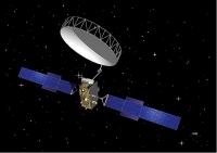
Figure 13: Artist's rendition of AlphaSat (image credit: ESA)
Payloads of Alphasat I-XL:
Alphasat I-XL carries a commercial payload for Inmarsat - a new generation of advanced geomobile communications payload in L-band (1.6 GHz) that will augment Inmarsat’s BGAN (Broadband Global Area Network) service, enabling communications across Europe, Asia, Africa and the Middle East with increased capacity. Alphasat I-XL features a new-generation digital signal processor for the payload, and a 12 m Ø aperture antenna reflector. AlphaSat I-XL is designed with increased capacity, 750 channels and 400-500 spot beams.
Alphasat I-XL also carries the hosted TDPs (Technology Demonstration Payloads) for ESA (European Space Agency). 27)
Note: Only a few aspects of the commercial payload can be provided (due to a lack of information); the intent is to provide an overview of the hosted payloads of ESA.
Integrated Processor (IP): The IP, developed for the Alphasat mobile mission, is the latest evolution of Astrium’s Digital Signal Processors product line – a technology that, for space applications. It is based on Astrium Next Generation Processor modular technology, which can be applied for other applications such as broadband and military missions (Ref. 10).
Astrium’s eight IPs are a core element of the leading-edge geomobile L-band communications payload, allowing allocation of capacity with an unprecedented flexibility through digital channelization and beamforming. It represents a major step forward in payload operational capability and commercial competitiveness.
The primary function of Alphasat’s IPs is the routing and combining of channels to the desired beam. They are the key elements for the generation of spot beams and associated channel gain. This provides Alphasat with maximum flexibility in both frequency and power allocation to beams to meet traffic demands.
Figure 14: Photo of the IP assembly (image credit: Astrium)
The 8 IPs have a mass of ~ 250 kg and use the latest electronics technology to work in parallel on board Alphasat. The DPM (Digital Processing Module )in each IP includes 17 large ASICs (core computers) which contain all of the complex digital processing for routing and beam forming, providing Alphasat with a processing capacity which is unprecedented on board a commercial satellite: it can perform more than 10 trillion calculations per second!
Deployable AstroMesh Reflector of commercial payload:
Astro Aerospace of Carpentaria, CA (USA), a strategic business unit of Northrop Grumman Corporation, has delivered its fourth deployable AstroMesh reflector to Astrium in Toulouse, France, this one for the Alphasat I-XL spacecraft that will provide commercial, broadband telecommunications services (L-band) to Europe, the Middle East, Africa and parts of Asia. 28) 29)
The reflector of 12 m aperture is the latest in a line of successful AstroMesh deployable, large aperture reflectors developed and built by Astro Aerospace. The reflector is a key part of the antenna system used by the spacecraft to provide broadband Internet communications. Enabled by the large reflector, the antenna system's sensitivity allows the use of mobile, laptop-size modems by users around the world.
Once the Alphasat satellite reaches orbit, ground controllers issue commands that control three hinge motors that unfold a 6 m boom supporting the reflector above the satellite. Additional ground commands are sent to two motors that unfurl the reflector to its fully deployed size.
• 112 kg subsystem mass (including boom & attachment hardware)
• 41 kg reflector only mass.
Alphasat I-XL features a new generation digital signal processor for the commercial payload.
Figure 15: Photo of the deployed AstroMesh reflector (image credit: Astro Aerospace)
Hosted TDPs (Technology Demonstration Payloads: LCT, Q/V-band transponder, Star Tracker, AEEF)
As a cost-effective way to deploy new services, validate new technologies, give them ‘flight heritage’ in space and introduce them in the commercial market, the concept of ‘hosted payloads’ offers a win-win-win solution for operators, industry and public institutions alike. 30) 31)
Hosted payloads benefit from available capacity on commercial satellites to accommodate additional transponders, instruments, or other applications that have to be operated in space. Partners share the satellite platform. This arrangement takes less time and money to implement, allowing advances in satcom technologies and services and new businesses to grow. This concept has also been referred to as ‘piggybacking’, ‘hitchhiking’ or secondary payloads.
Through ARTES, ESA has supported a number of hosted payloads over the years. These include the launch of the Skyplex processor payload on the Hot Bird 4 satellite of Eutelsat (launch Feb. 27, 1998 into GEO), followed by AmerHis on Amazonas 1 (AmerHis is the first operational regenerative, onboard processing, satellite switching system in the world, launch August 5, 2004). AmerHis has enabled Hispasat (Spanish telecommunications satellite service provider) to provide high-performance interactive multimedia services on its four Ku-band coverage zones: North America, South America, Brazil and Europe. The AmerHis system is an innovative solution of satellite broadband mesh communication based on a regenerative DVB-S/DVB-RCS processor.
Figure 16: Photo of AlphaSat during encapsulation on July 15, 2013 (image credit: ESA,Ref. 31)
Legend to Figure 16: AlphaSat carries a quartet of test technologies on its side: Q/V-band transponder, AEEF,Star Tracker, and LCT. The first and last of these are particularly conspicuous due to their covering of gold-coloured foil.
LCT (Laser Communication Terminal - TDP1):
Developed by Tesat Spacecom (Germany) and Ruag Space (Switzerland) with funding from DLR (German Space Agency) and the Swiss Space Office, and coordinated by ESA, this TDP (Technology Demonstration Payload) is a data relay mission to link observation data from LEO observation satellites towards a ground station through the geostationary Alphasat. The data-relay link between LEO and GEO will enable direct downloads from Earth observation satellites to small terminals, allowing for example, rescue workers to see near-realtime satellite imagery of the region where they are working. The LCT instrument is of TerraSAR-X, NFIRE (DoD) and TanDEM-X mission heritage. 32) 33)
Figure 17: Tesat 2nd generation LCT instrument showing the space side with hemispherical coarse pointing unit (image credit: Tesat)
The LCT provides a 2 Gbit/s bidirectional data link between the LEO satellite and the Alphasat I GEO satellite using laser diode pumped Nd:Yag (neodymium-doped yttrium aluminum garnet) crystal lasers transmitting infrared light at an ultrastable wavelength of 1.064 µm.
The LCT includes two major functions: to relay Earth observation data from LEO satellites (for example, Sentinel-1), and to verify the bidirectional optical link (experiment results, such as error counts, sensor data, etc., are transmitted via Alphasat telemetry to the ground for evaluation).
The major advantage of laser communication terminals compared to conventional RF payloads is their very high data rate, and this is the first time that such an optical LEO-to-GEO link will be verified in orbit. This TDP is a precursor of an operational optical communication system that will be used for ESA's EDRS (European Data Relay System).
The satellite laser terminal acquires the very weak signal from the optical beam of an optical counter terminal, which may be up to 50 000 km away. Once acquired, the data transmission between the two laser terminals (LEO and GEO) starts. Considering that LEO satellites travel at ~ 8 km/s (28,000 km/h), and the GEO satellite at about 3 km/s (11,000 km/h) in different directions, accomplishing this link is indeed a big challenge.
The received data are then downlinked via the Ka-band transmitter to the DLR ground station. More than ten LEO-to-GEO links per day in the first years of operation are expected.
|
Optical link |
LEO-GEO full duplex communication |
|
Data rate |
2.8 Gbit/s (1.8 Gbit/s user data) |
|
Link distance |
> 45,000 km |
|
BER (Bit Error Rate) |
10-8 |
|
Optical transmit power |
2.2 W |
|
Telescope diameter |
135 mm |
|
LCT instrument mass, power |
54 kg, 160 W |
|
Instrument size |
0.6 m x 0.6 m x 0.7 m |
Table 3: Key design features for LCT LEO-GEO relay 34)
On May 3, 2012, the laser terminal arrived in Toulouse, France, from Backnang, Germany, and has now been bolted to the Earth-facing part of Alphasat. 35) 36)
The LCT block diagram is shown in Figure 18. Major changes are: For the 2nd generation LCT an off-axis telescope is chosen, the optical power amplifier is changed to a 5 W device, the receiver is optimized for a user data rate of 1.8Gbit/s. For GEO applications, the electronics were redesigned to operate the adapted devices and to match with the GEO radiation environment for 15 years of continuous service. The thermal system is improved, the mechanics scaled for the bigger units.
LCT generic design/qualification approach: The LCTs are built such, that the LCTs for GEO and LEO application are same for its units design and their qualification. The GEO and LEO LCTs have identical optical space interfaces with same performance. For adaptation of the generic design to the 2nd generation LCT to S/C application, only the spacecraft interface related items (e.g. bus voltage, TM/TC interface and thermal interface) are modified. In Figure 19. the AlphaSat LCT is seen with its customized thermal interface for the AlphaSat spacecraft.
Figure 18: Block diagram of the LCT instrument (image credit: Tesat)
Figure 19: Alphasat LCT, equipped with MLI, with an Alphasat specific thermal Interface, mounted in its transportation frame (image credit: Tesat)
Figure 20: AlphaSat data relay payload (image credit: Tesat) 37)
Q/V-band transponder payload (TDP5) / Aldo Paraboni Payload:
The Q/V-band payload, developed by TAS-I (Thales Alenia Space-Italia) and Space Engineering, has the objective to assess the suitability of this millimeter-wave band for future commercial applications. The propagation package will allow beacon measurements throughout Europe at Ka-band (19.704 GHz) and Q-band (39.402 GHz). The TDP5 payload is funded by ASI (Agenzia Spaziale Italiana). 38) 39) 40) 41) 42)
In the summer of 2013, ASI decided to rename the Q/V transponder payload to “Aldo Paraboni Payload” in memory of the late Professor Aldo Paraboni, who died on April 13, 2013 and who had dedicated his academic life to space telecommunications research in all ASI projects. 43)
Advantages and today's limitations of Q/V-bands: 44)
• Larger bandwidth
• Smaller antenna for fixed gain
• Higher gain for fixed antenna
• Enhanced directivity for spot beams systems
• Increase of atmospheric impairments
• Research activities needed
• Different design approach: a) FMT(Fade Mitigation Technique), b) lower QoS (Quality of Service).
Given the very strong atmospheric fading that can be experienced at Q/V frequencies, the communication experiment is aimed at demonstrating the capability of IFMT (Interference and Fading Mitigation Techniques), and site diversity in improving the link quality in a real Q/V band satellite link.
In 2009, ASI (Italian Space Agency) invited Austria to join the TDP5 experiments. Thanks to the support by the Austrian Aeronautics and Space Agency, it was decided that a Q/V-band ground station will be established in Graz to be able to carry out joint communications and propagation experiments with the Italian partners: ASI, Space Engineering, Politecnico di Milano, and Università Tor Vergata of Rome. As a consequence of these agreements, it was decided to redirect the third beam of the Q/V-band payload to be centered over Austria. Joanneum Research and Graz University of Technology (TU Graz) are the Austrian partners in the Q/V-band payload preparing for communications and propagation experiments.
The main goal of the communications experiments is the investigation of ACM (Adaptive Modulation and Coding) techniques. At millimeter-waves the propagation effects can be very significant. A conventional system design with large fade margins is impractical, as this leads to high EIRP and G/T figures for the ground stations resulting in unacceptable costs. Fade mitigation techniques by adaptive coding and modulation offer a cost-effective solution to this problem.
In the framework of several ESA activities a meshed VSAT system has been developed which uses an advanced MF-TDMA demand assignment access scheme and an adaptive modem and Turbo codec. The synchronization algorithms for the modem have been optimized such that the modem can operate at a very low signal/noise ratio. This platform is ideal for the ACM experiments. The propagation studies and measurements will provide the data for the fade depths, fade slopes and scintillation effects. Based on the measurement results, the ACM algorithms will be optimized and verified in the communications experiments.
The block diagram of the Alphasat Q/V-band transponder is shown in Figure 22. The payload configuration can be seen in Figure 23. The two antennas have a diameter of 35 cm x 42 cm. The nominal output power of the transponder is 5 W at Q-band.
Figure 21: Photo of the Q/V-band communication repeater - also referred to as QVCA (image credit: TAS-I)
The QVCA (Q/V-band Communication Antenna) service area is composed of 3 ground stations. The beam centers have been defined for communications with three ground stations located at:
1) IT1: Tito Scalo (40º35’55” N, 15º43’23“ E), in southern Italy
2) IT2: Spino d’Adda (45º24’ N, 9º29‘E), in northern Italy
3) EU1: Graz (47º05‘07” N, 15º27’54“ E), Austria
The transponders can be operated in different configurations: cross-strapped or loop-back (Figure 23). In the cross-strap mode, any two beams can be interconnected, leaving the third beam idle. The space-to-Earth center frequencies are 37.9 and 38.1 GHz.
The maximum EIRP of the transponder is 39 dBW, when remaining in the linear mode. The polarization is linear vertical to take advantage of the fact that the vertical polarization is less affected by rain fade than the horizontal plane. The Earth-to-space frequencies are 47.9 and 48.1 GHz. The figure of merit (G/T) of the transponder yields 4.4 dB/K (taking into account the spacecraft movement). A transponder channel bandwidth of 10 MHz is available.
Since the Q/V-band payload is a secondary and an experimental one, the EIRP and G/T are comparatively low, requiring relatively powerful ground stations.
Figure 22: Alphasat Q/V-band payloads block diagram including propagation section (image credit: ASI)
Figure 23: Modes of operations: Cross-strap mode (left), Loop-back mode (right), image credit: TU Graz
The block diagram of the ground station is shown in Figure 24. VHL (70/140 MHz) as well as L-band interfaces will be provided for maximum flexibility. The 70/140 MHz signal will be upconverted to L-band by a converter unit. In a second stage, the signal will be translated to the transmit frequency of 47.9 or 48.1 GHz and fed to a driver amplifier. Its output drives the HPA (High Power Amplifier). At the output of the power amplifier, a remote-controlled waveguide switch connects either to the antenna or a dummy load. Prior to the dummy load, a test signal is available via a 40 dB coupler which can be connected to a spectrum analyzer, a counter or the test translator, converting the V-band signal to Q-band.
Since only a single polarization is used (vertical), no ortho-mode transducer is required. However, a high-performance diplexer is needed. At the V-band port, the HPA is connected, whereas the LNA is directly attached to the Q-band port. At its output a coupler or switch allows to feed in the test translator output signal, when the station is in test mode. This configuration avoids degrading the system noise figure by a coupler or waveguide switch at the LNA input. The amplified Q-band signal is down-converted to L-band where it is directly available for L-band communications systems. If terminals with 70/140 MHz interfaces have to be used, a second down-converter from L-band will be utilized.
Figure 24: Block diagram of the Alphasat ground terminal (image credit: TU Graz)
The tracking system will be either monopulse or step-track depending on the antenna size which will be finally chosen. In principle, program track could be used as well, but this prerequisites excellent-quality and up-to-date Kepler elements.
The propagation receiver, which has to measure a cross-polar Q-band beacon and a vertically polarized Ka-band beacon will be connected to a separate co-located antenna. This avoids a very complicated and expensive feed and front-end. This decision was supported by the fact that the already well advanced beacon receiver project will get its own antenna with tracking from ESA.
Figure 25: Overview of the Q/V-band ground stations in the TDP5 payload (image credit: ASI)
Figure 26: Alternate view of the TDP5 ground system (image credit: Space Engineering S.p.A., ASI) 45)
• TDP5 features two fully redundant beacon transmitters operating at Ka-/Q-band. The Ka-band beacon at 19.7 GHz covers Europe and North Africa (Figure 27). The polarization is linear vertical. The Q band beacon at 39.4 GHz covers Europe with a maximum antenna gain over Milano (Figure 28). The Q-band beacon polarization is linear NW-SE (45° tilted). Table //earth.esa.int/web/eoportal/satellite-missions/a/alphasat#Su@NI13d8Herb" style="color: rgb(0, 155, 207);">4 summarizes the Alphasat beacon characteristics. 46)
|
Parameter |
Ka-band |
Q-band |
|
Frequency |
19.701 GHz |
39.402 GHz |
|
Polarization |
linear vertical |
linear tilted 45º |
|
Antenna boresight |
32.5º N, 20º E |
45.4º N, 9.5º E |
|
EIRP (Effective Isotropic Radiated Power) |
19.5 dBW |
26.5 dBW |
Table Su@NI13d8Herb" style="color: rgb(0, 155, 207);" name="Su@NI13d8Herb">4: Main characteristics of Alphasat TDP5 beacons
Figure 27: Alphasat TDP5 beacon coverage of the Ka-band, 19.701 GHz 47)
Figure 28: Alphasat TDP5 beacon coverage of the Q-band, 39.402 GHz
Star Tracker (TDP6):
Developed by Jena Optronik GmbH (Germany), the Astro APS (Active Pixel Sensor) star tracker is included to gain early flight heritage on this new product. It is capable of very accurate and autonomous attitude acquisition. The sensor is highly resilient to the radiation experienced in geostationary orbits. 48) 49)
Figure 29: Photo of the Astro APS star tracker (image credit: Jena Optronik)
Star trackers are used for attitude control of current generation communication satellites. By using stars as reference points, star trackers are help to make sure that a satellite keeps in the same position and points in the right direction. The higher the accuracy, the better a satellite can operate and spend less fuel, allowing a longer life in orbit. A star tracker can be heavily influenced by the radiation and sunlight. Jena Optronik’s new generation of star tracker offers higher precision.
The Astro APS uses the most radiation hard CMOS Active Pixel Sensor on the market, the STAR1000. Each pixel has an individual readout, thereby avoiding “blooming” of charge over to neighboring pixels. This improves performance with bright objects in the field of view, e.g. the moon. The centroid calculations are done on the same integrated circuit resulting in tracking rates, e.g. 10 Hz, that are much faster than CCD-based star trackers. Built-in software algorithms automatically identify and compensate for anomalies such as white spots. A Peltier cooler is included. The star sensor is a single unit with camera head, electronics, and a shorter baffle than on CCD-based star trackers.
|
Instrument size |
154 mm x 154 mm x 231 mm |
Including baffle |
|
Instrument mass (sensor + baffle) |
1.980 kg for GEO mission 18 years |
1.500 kg for LEO missions |
|
Optical design |
|
|
|
Operational temperature range |
-30ºC to +60ºC |
|
|
FOV (Field of View) |
20º (circular) |
|
|
Data interface |
MIL-STD-1553B, RS422 |
SpaceWire |
Table 5: Performance of ASTRO APS
AEEF (Alphasat Environment Effects Facility - TDP8):
The AEEF is designed and developed by the EFACEC group (Portugal) in cooperation with the University of Aveiro (Portugal) and DAS Photonics (Valencia, Spain). The objective of AEEF is to test electronic components and solid-state materials in the radiation environment of a geostationary orbit. An energy selective particle spectrometer measures these radiation levels in parallel (Ref. 30). 50) 51) 52)
AEEF is comprised of a number of different elements measuring specific environments and effects together with dedicated hardware for data storage and interface to the spacecraft. The environments monitored include:
• High energy radiation (from the radiation belt, solar flares and cosmic rays)
• Low energy electrons
• Micrometeoroids and debris.
Additionally, AEEF includes a Component Technology Test Bed to investigate the effects of radiation on components (particularly of interest to the Alphasat payload). The following effects are monitored:
• Single event effects (e.g. single event upsets, single event transients)
• TID (Total Ionizing Dose) degradation (specifically of interest in the electron rich Alphasat environment)
• DD (Displacement Damage) to optoelectronics and detectors, and radiation background in sensors.
The objectives include full validation of hardening methods used in design, validation of new testing and analysis methods and demonstration of novel EEE (Electrical, Electronic and Electromechanical) component technologies. Additionally the validity of ground-based testing compared to in-flight results will be studied.
Figure 30: Illustration of the AEEF assembly (image credit: ESA, EFACEC)
AEEF includes two technology demonstration boards: one SIOS (Sistema de Interconexiones Ópticas para Satélites) optical link demonstration board and one GaN (Gallium Nitride) board. The SIOS optical link demonstration board will include 4 low data rate (1 Mbit/s) and 4 medium data rate (100 Mbit/s) optical links, with different power budgets among them to check the impact on each power output in flight conditions. The experiment will be running during 3-5 years, testing their power consumption and monitoring BER in real flight conditions. 53) 54)
Figure 31: EQM (Engineering Qualification Model) of the SIOS experiment for AEEF (image credit: DAS Photonics)
GaN (Gallium Nitride): GaN is currently used in terrestrial applications such as LEDs (Light Emitting Diodes) and radio frequency applications up to 60 GHz. It provides several advantages compared to more conventional semiconductor technologies based on Silicon and GaAs (Gallium Arsenide). The most important feature is its high breakdown voltage (10-fold when compared to Si) allowing for compact high speed devices with significantly increased output power. For space applications, its reduced sensitivity to cosmic radiation is of particular importance and a decisive advantage over Si devices. 55)
The AEEF assembly has a mass of 10 kg, a total power consumption of < 25 W EOL, and a nominal lifetime of 3 years. AEEF will be monitored at Inmarsat, London and at the ESA TDP Coordination Office (Ref. 52).
AlphaSat I-XL ground segment:
The AlphaSat I-XL satellite is developed through a Public Private Partnership (PPP) between Inmarsat and ESA. AlphaSat will be integrated into the Inmarsat satellite fleet to provide mobile satellite communications services for users in the maritime, land and aviation sectors. It will provide coverage over Europe, Asia, Africa and the Middle East.
The AlphaSat services and ground segment developments are developed in partnership with ESA as part of the PPP with Inmarsat. Those activities cover the design and development of new services, ground segment infrastructure, user terminal technology and applications with the aim to fully exploit the capabilities of AlphaSat.
1) “ARTES 8 Alphabus/Alphasat,” ESA, last update Dec. 2013, URL: undefined
2) “Inmarsat and Astrium sign Alphasat I-XL satellite contract,” Nov. 23, 2007, URL: undefined
3) “Alphabus equipment phase C/D selection,” ESA, Sept. 22, 2005, URL: undefined
4) “ARTES 8 Alphabus/Alphasat,” ESA, last update Dec. 16, 2013, URL: undefined
5) Andreas Mauroschat, Stéphane Lascar, Thibéry Cussac, Michel Roux, Marc Patier, “Alphabus: Europe’s solution for the high-power satcom market,” ESA Bulletin No 142, May 2010, URL: undefined
6) “Alphabus: An Extended European Capability,” ESA, Oct. 28, 2010, URL: undefined
7) Thibery Cussac, Stephane Lascar, Andreas Mauroschat, Patrick Dumont, “Alphabus, a successful European Public Private Partnership,” Proceedings of the 61st IAC (International Astronautical Congress), Prague, Czech Republic, Sept. 27-Oct. 1, 2010, IAC-10.B2.1.7
8) “When a bus becomes a satellite,” ESA, March 16, 2011, URL: undefined
9) “More power to Alphabus,” ESA, April 4, 2011, URL: undefined
10) “ A communications satellite with vision,” Astrium, June 18, 2013, URL: undefined
11) “Alphabus ready to offer new opportunities,” Space Daily, June 23, 2011, URL: undefined
12) “Alphabus Fact Sheet,” ESA, May 5, 2011, URL: undefined
13) “Alphabus/Alphasat,” ESA, January 8, 2011, URL: undefined
14) “First voyage for Alphabus Service Module,” ESA, Jan. 29, 2010, URL: undefined
15) “Alphabus: An Extended European Capability,” ESA, January 16, 2010, URL: undefined
16) L. Soubrier, E. Trehet, “High Power PCU for Alphabus: PSR100V,” Proceedings of the 9th European Space Power Conference, Saint Raphael, France, June 6-10, 2011, ESA SP-690
17) “Power Supply Regulator (PSR) - 100V,” EADS Astrium, URL: undefined
18) “Alphasat reaches key ground-testing milestone,” Inmarsat, Nov. 26, 2012, URL: undefined
19) “AlphaSat status,” ESA Bulletin, No 153, February 2013, p. 74
20) “Alphasat's journey to meet its launcher,” ESA, July 3, 2013, URL: undefined
21) “Flawless launch of AlphaSat, Europe's largest and most sophisticated telecom satellite,” ESA, July 25, 2013, URL: undefined
_largest_and_most_sophisticated_telecom_satellite
22) “Alphasat I-XL – a quantum leap for satellite communications,” DLR, July 25, 2013, URL: undefined
23) “Apphasat's pioneering high-frequency hosted payload set for experiments,” ESA, January 21, 2014, URL: undefined
24) “Astrium-built Alphasat satellite ready for service at its operational orbital position,” Astrium Press Release, Nov. 20, 2013, URL: undefined
25) “AlphaSat's Laser Terminal on target,” ESA, Nov. 11, 2013, URL: undefined
26) “AlphaSat deploys its giant reflector in orbit,” ESA, Aug. 5, 2013, URL: undefined
27) “Hosted payloads given green light,” ESA, June 16, 2011, URL: undefined
28) Northrop Grumman's Astro Aerospace Delivers Deployable Reflector to Astrium for Alphasat I-XL Spacecraft,” Astro Aerospace, May 9, 2011, URL: undefined
29) “Northrop Grumman's Astro Aerospace Delivers Deployable Reflector to Astrium for Alphasat I-XL Spacecraft,” Space Mart, May 10, 2011, URL: undefined
_Deployable_Reflector_to_Astrium_for_Alphasat_IXL_Spacecraft
30) Andreas Mauroschat, Stephane Lascar, Rudolf Halm, Francois Garat, Kevin Goodey, Xavier Lobao, Fabrice Joly, “Hitching a ride to orbit: The 'hosted payloads' concept,” ESA Bulletin, No 148, November 2011, pp. 33-41, URL: undefined
31) “High-Tech Hitchhikers,” ESA, July 24, 2013, URL: undefined
32) Gerd Muehlnikel, Hartmut Kämpfner, Frank Heine, Herwig Zech, Daniel Troendle, Rolf Meyer, Sabine Philipp-May, “The Alphasat GEO Laser Communication Terminal Flight Acceptance Tests,” Proceedings of the ICSOS (International Conference on Space Optical Systems and Application) 2012, Ajaccio, Corsica, France, October 9-12, 2012, URL: undefined
33) Matthias Motzigemba, “Improvement of information latency in EO-Missions with the use of hybrid Laser/RF systems,” Proceedings of the 64th International Astronautical Congress (IAC 2013), Beijing, China, Sept. 23-27, 2013, paper: IAC-13-B2.2.3.9
34) F. Heine, H. Kämpfner, R. Lange, R. Czichy, R. Meyer, M. Lutzer, “Optical Inter-Satellite Communication Operational,” 2010 Military Communications Conference, San Jose, CA, USA, Oct. 31-Nov. 3, 2010, URL: undefined
35) “Advanced laser technology on the way to space,” ESA, May 30, 2012, URL: undefined
36) Dominique Elser, Stefan Seel, Frank Heine, Thomas Länger, Momtchil Peev, Daniele Finocchiaro, Roberta Campo, Annamaria, Thomas Scheidl, Rupert Ursin, Zoran Sodnik, “Network Architectures for Space-Optical Quantum Cryptography Services,” Proceedings of the ICSOS (International Conference on Space Optical Systems and Application) 2012, Ajaccio, Corsica, France, October 9-12, 2012
37) Philipp Wertz, Wolfgang Griethe, “High Data Rate Transmission for Earth Observation and ISR Missions using Next Generation Downlink Subsystems and Free-Space Optical Communications,” First Workshop on Ka-band Earth Observation Radar Missions, KEO'12, Noordwijk, The Netherlands, Nov. 5-9, 2012
38) Otto Koudelka, “Q/V-band Communications and Propagation Experiments Using AlphaSat,” Proceedings of the 61st IAC (International Astronautical Congress), Prague, Czech Republic, Sept. 27-Oct. 1, 2010, IAC-10.B2.1.8
39) Piero Gabellini, Luciano D'Agristina, Luciano Dicecca, Domenico Di Lanzo, Nicola Gatti, Jean-Christophe Angevain, “The Electrical Design and Verification of the AlphaSat TDP5 Antenna Farm,” Proceedings of the 32nd ESA Antenna Workshop on Antennas for Space Applications, Noordwijk, The Netherlands, Oct. 5-8, 2010, URL: undefined
40) O. Koudelka, M. Schmidt, J. Ebert, “Design of a 40/50 GHz Satellite Ground Station for Fade Mitigation Experiments,” Proceedings of IAC 2011 (62nd International Astronautical Congress), Cape Town, South Africa, Oct. 3-7, 2011, paper: IAC-11.B2.2.7
41) Piero Gabellini, Domenico Di Lanzo, Luciano D'Agristina, Jean-Christophe Angevain, Luciano Dicecca, Paolo Proietti Zolla, Gianfranco Sordetti, Luis Rolo, “Test and verification of the AlphaSat TDP5 Q/V-band communication Antenna,” Proceedings of 33rd ESA Antenna Workshop on Challenges for Space Antenna Systems, ESA/ESTEC, Noordwijk, The Netherlands, Oct. 18-21, 2011
42) Giuseppe Codispoti, “Fostering fast telecommunications developments trough the use of Q/V band satellite links,” Proceedings of the 49th Session of UNCOPUOS-STSC (UN Committee on the Peaceful Uses of Outer Space-Scientific and Technical Subcommittee), Vienna, Austria, Feb. 6-17, 2012, URL: undefined
43) “AlphaSat Payload Honors Aldo Paraboni,” ESA, URL: undefined
44) Giuseppe Codispoti, “IInvollvement of Diigiitall Diiviide affected countriies iin Q//V Band experiimentatiion and use,” Proceedings of the 50th Session of Scientific & Technical Subcommittee of UNCOPUOS, Vienna, Austria, Feb. 11-22, 2013, URL: undefined
45) Carlo Cornacchini, Antonio Vernucci, Giuseppe Codispoti, Enrico Russo, “The Alphasat TDP#5 Mission Segment,” URL: undefined
46) Franz Teschl, Otto Koudelka, “Design and first test of a combined 19.7 and 39.4 GHz beacon receiver for the Alphasat propagation experiment,” Proceedings of the 64th International Astronautical Congress (IAC 2013), Beijing, China, Sept. 23-27, 2013, paper: IAC-13-B2.5.2
47) M. Ruggieri, C. Riva, M. De Sanctis, T. Rossi, “ Alphasat TDP#5 mission: Towards future EHF satellite communications,” Proceedings of ESTEL 2012 - First IEEE-AESS European Conference on Satellite Telecommunications, 2-5 October 2012, Rome, Italy
48) “Active Pixel Sensor ASTRO APS,” URL: undefined
49) “AlphaSat carries new space compass,” ESA, July 15, 2013, URL: undefined
50) “Alphasat TDP#8: Environment and Effects Facility (AEEF),” ESA, Oct. 28, 2008, URL: undefined
51) “Reading Radiation in Space,” ESA, May 21. 2013, URL: undefined
52) “Environmental Testing and Radiation Sensor,” ESA factsheet, URL: undefined
53) Julián Blasco, Eloy Rico, Pablo Genovard, Cristina Sáez, Olga Navasquillo, Javier Martí, “DAS Photonics Developments For Analogue And Digital Photonics Links For Intrasatellite Communications,” Proceedings of the ICSO (International Conference on Space Optics), Ajaccio, Corse, France, Oct. 9-12, 2012, paper: ICSO-102, URL: undefined
54) J. Blasco, O. Navasquillo, C. Sáez, “Digital and Analogue Optoelectronic Links for Intrasatellite Communications,” ICSO 2010 (International Conference on Space Optics), Rhodes Island, Greece, Oct. 4-8, 2010, URL: undefined
55) Nuno Borges de Carvalho, Hugo Mostardinha, Pedro Cabral, “The first European GaN Experiment in Space,” URL: undefined
The information compiled and edited in this article was provided by Herbert J. Kramer from his documentation of: ”Observation of the Earth and Its Environment: Survey of Missions and Sensors” (Springer Verlag) as well as many other sources after the publication of the 4th edition in 2002. - Comments and corrections to this article are always welcome for further updates.


