The Sentinel-4 (S-4) mission within the context of Copernicus represents the geostationary component of European (EC, ESA) operational atmospheric composition monitoring missions.
In December 2007, the GMES Atmospheric Service Implementation Group of the EC (European Commission), issued its preliminary recommendations for the development of the GMES Space Segment operational capabilities in regard of atmospheric missions. In particular, it recommended implementing the Sentinel-4 mission as a UVN (UV/Visible/Near-infrared) sounder to be deployed on the two MTG Sounding (MTG-S) satellites. 1) 2) 3) 4) 5) 6)
|
Copernicus is the new name of the European Commission's Earth Observation Programme, previously known as GMES (Global Monitoring for Environment and Security). The new name was announced on December 11, 2012, by EC (European Commission) Vice-President Antonio Tajani during the Competitiveness Council. In the words of Antonio Tajani: "By changing the name from GMES to Copernicus, we are paying homage to a great European scientist and observer: Nicolaus Copernicus (1473-1543). As he was the catalyst in the 16th century to better understand our world, so the European Earth Observation Programme gives us a thorough understanding of our changing planet, enabling concrete actions to improve the quality of life of the citizens. Copernicus has now reached maturity as a programme and all its services will enter soon into the operational phase. Thanks to greater data availability user take-up will increase, thus contributing to that growth that we so dearly need today." |
Table 1: Copernicus is the new name of the former GMES program 7)
The objective of Sentinel-4 is to monitor key air quality trace gases and aerosols over Europe at high spatial resolution with a fast (hourly) revisit time in support of the GMES Atmosphere Service. The objective of the LEO missions, S-5 and S-5P, is to measure daily at global scale and high spatial resolution air quality and climate related trace gases and aerosols in the Earth's atmosphere. The target species including O3, NO2, SO2, HCHO and aerosols shall be observed to support operational services covering air-quality near real-time applications, air-quality protocol monitoring and climate protocol monitoring.
The S-4 system consists of an UVN (Ultra-violet Visible Near-infrared) imaging spectrometer embarked on EUMETSAT's geostationary MTG-S platforms and relies on the utilization of subsets of data from EUMETSAT's IRS sounder on-board the same platforms and from EUMETSAT's FCI imager on-board the MTG-I platforms. S-5 UVN and SWIR (UVNS) is planned to be embarked on EUMETSAT's EPS-SG series of satellites, while S-5P will fly on a dedicated platform. 8)

Figure 1: Coverage requirements of the UVN sounder defined by the yellow rectangle (image credit: ESA)
Considering the severe polarization sensitivity requirement and the sounder mass and volume constraints (140 kg), the concept that has been selected is a polarization scrambler to make the instrument insensitive to polarization. The concept of measuring polarization with high spectral resolution has not been retained due to the increased complexity and mass.
The Sentinel-4/5 and Sentinel-5 precursor missions will be devoted to atmospheric composition monitoring for the GMES Atmosphere Service. There will be two families of atmospheric chemistry monitoring missions, one in geostationary orbit (Sentinel-4) and one in low Earth orbit (Sentinel-5 precursor, Sentinel-5).
The Sentinel-4 mission will consist of an UVN (Ultraviolet-Visible-Near-Infrared) spectrometer accommodated on Meteosat Third Generation Sounder (MTG-S) platforms. Two missions are planned of the S-4 UVN payload: the first one in 2019 and the follow-up mission in 2027.
The Sentinel-4 GEO component mission has been approved by the ESA Council in 2008. - At EUMETSAT, the full MTG (MeteoSat Third Generation) program, which includes all the major development/procurement activities and the routine operations phase, was planned to start by January 2011 as a result of the approval process initiated by the 70th EUMETSAT Council held in Rome in June 2010. Because the approval process was taking longer than expected, the EUMETSAT Council in December 2010 debated authorizing the full start of MTG work as of January 2011 in parallel with the finalization of voting for those Member States which could not complete it by the Council itself. The EUMETSAT Council resolution, approving the full MTG program, entered into force on February 25, 2011. 9)
Note: The MTG series spacecraft are described in the MTG file on the eoPortal.

Figure 2: Artist's view of the deployed Sentinel-4 mission spacecraft with the UVN spectrometer (image credit: ESA) 10)
Sentinel-4 mission implementation status:
• S4/UVN instrument & Level-1b Prototype Processor developed by ESA with Airbus Defence & Space as prime (Ref: 10)
- PDR (Preliminary Design Review) completed
- Intermediate Instrument Performance Review end 2015
- CDR (Critical Design Review) mid 2016
- FAR (Flight Acceptance Review) early 2021
• Level-1b geometric processing developed on platform level
• Level-2 Operational Processor developed by ESA with DLR as prime
- Kick-off 2 June 2015
- Prototype and Operational Processor
- System Integration & Verification, support to Commissioning
• EUMETSAT will operate the instrument and process the mission data up to Level-2.
Launch: The Sentinel-4A (S4A) payload will be launched onboard the first EUMETSAT spacecraft MTG-S (Meteosat Third Generation-Sounder) with a planned launch in 2021 — actually a CFI (Customer Finished Item) and a hosted payload on MTG-S.
Orbit: Geostationary orbit, located at ~0º longitude.
Sentinel-4 mission sensor complement: (UVN)
On July 11, 2011, ESA awarded a contract to Airbus DS (Ottobrunn, Germany), formerly Astrium, to develop and build two satellite sensors that will monitor Earth's atmosphere as part of Europe's Copernicus program. The identical spectrometers, known as Sentinel-4, will each be carried on the MTG (Meteosat Third Generation) weather satellites, to be launched in 2019 and 2027, respectively. 11)
The Sentinel-4 system consists of an UVN (Ultra-violet Visible Near-infrared) imaging spectrometer embarked on the EUMETSAT's geostationary MTG-S platforms and relies on the utilization of subsets of data from EUMETSAT's IRS (Infrared Sounder) on-board the same platforms and from EUMETSAT's FCI (Flexible Combined Imager) imager data on-board the MTG-I platforms.
The Sentinel-5 UVN and SWIR (UVNS) sounder is planned to be embarked on EUMETSAT's EPS-SG series of LEO satellites (i.e. MetOp-SG series), while the Sentinel-5P mission will fly on a dedicated platform.
UVN (Ultraviolet-Visible-Near-Infrared) Spectrometer:
The UVN instrument is a wide-field pushbroom hyperspectral imaging spectrometer, a sounder, that scans Europe in the East-West direction with a repeat cycle of 60 minutes. The FOV is about 9º in the East-West direction and about 3.4º in the North-South direction, centred on Europe. The UVN spectrometer features bands in the UV and VIS (305-500 nm) with a spectral resolution of 0.5 nm, and in the NIR (750-775 nm) spectral ranges with a spectral resolution of 0.12 nm, in combination with low polarization sensitivity and a high radiometric accuracy. 12) 13) 14)

Figure 3: Spectral coverage of the UVN Sounder (image credit: ESA)
|
Band |
Spectral range (nm) |
Spectral |
SSD |
SNR @ 50ºN, 15:00 UTC, Equinox, albedo 0.05 (UV-VIS) & 0.15 (NIR) (per spectral sample) |
Spectral sampling ratio |
Species |
|
UV |
305-400 |
0.5 |
8 km |
200 - 1000 |
3 |
O3, SO2, BrO, HCHO, AAI, AOD, Ring |
|
VIS |
400-500 |
0.5 |
8 km |
1400 |
3 |
NO2, O4, IO CHOCHO, AOD |
|
NIR |
750-775 |
0.12 |
8 km |
600 |
3 |
Cloud, Aerosol |
Table 2: UVNS observation requirements
The instrument design enables a short revisit time from east to west in one hour with sufficient east-west spatial dimension, covering most of Europe and North Africa. The reference area and the larger geographical coverage areas are shown in Figure 4. The east-west spatial dimension is accounted for by scanning the scan mirror from east to west in one hour. With about 570 spatial samples in the east-west spatial dimension this corresponds to about 6 seconds per 8 km spatial sample.

Figure 4: Sentinel-4/UVN geographical coverage area (GCA) and reference area (RA), image credit: ESA)
Legend to Figure 4: OZA = Observation Zenth Angle.
UVN instrument:
The instrument will be composed of 3 units (Ref. 6):
• Main Optical Unit that contains the optical and detection part
• VEU (Video Electronic Unit)
• ICU (Instrument Control Unit).
At sunrise in the east the instrument only scans the illuminated Earth, resulting in a total scan time of less than one hour. In the evening the same scenario is followed in the west. During autumn-winter the coverage area is shifted twice south by 5º in order to optimize observation of illuminated areas, as shown in Figure 4. During winter-spring, the scenario is reversed.
An example for a possible East-West scan in the NEO (Nominal Earth Observation) mode is given in Figure //directory.eoportal.org/web/eoportal/satellite-missions/c-missions/copernicus-sentinel-4#L@uzI1daHerb" style="color: rgb(0, 155, 207);">5.

Figure L@uzI1daHerb" style="color: rgb(0, 155, 207);" name="L@uzI1daHerb">5: Example for a possible East-West scan pattern of the NEO mode (image credit: ESA)
The MTG-Sounder satellite embarking the S4/UVN instrument is in geostationary orbit at a longitude of about 0ºabove the equator. The accommodation of the instrument is optimized, allowing the Earth radiance, sun irradiance and thermal fields of view to be clear and unobstructed. Furthermore straylight from the sun or the Earth via other spacecraft components is minimized per design. This is particularly important for such class of space instrumentation for which the Level 1b and Level 2 data product accuracies are very sensitive to even small straylight contributions.
At the equinoxes, the MTG-S spacecraft performs a yaw-flip maneuver in order to keep the satellite and instrument thermal environment optimized. For the instrument this implies that the scan mirror has to adjust the north-south axis to keep the geographical coverage area in view and reverse the east-west scan axis in order to keep scanning from east to west. In addition, the sun observations are performed in the evening rather than in the morning, or vice versa, as a result of the spacecraft yaw-flip maneuver.
The instrument is equipped with two frame-transfer CCD (Charge Coupled Device) detectors, one for the UV-VIS wavelength range and one for the NIR wavelength range. One dimension on the CCDs corresponds to the spectral dimension, while the other dimension corresponds to the north-south spatial dimension.
In the wavelength range covered by Sentinel-4/UVN the light from the Earth's atmosphere can be strongly linearly polarized, which is accounted for in the instrument design by minimizing the overall instrument polarization sensitivity in combination with the use of a weak polarization scrambler. A refractive spectrometer design is the baseline with two separate spectrometers, one optimized for the Ultra-Violet (UV) and visible (VIS) wavelength range and the other for the 25 nm spectral band in the Near-Infra-Red (NIR).
The instrument's polarization sensitivity has to be balanced with the optical quality properties on the Earth, which is especially critical for an instrument in a geostationary orbit. Using a too strong polarization scrambler will result in too much blurring of the ground sampling distance on the Earth's surface. Another way of putting this is to say that the integrated energy within a ground pixel (spatial sample) will need to be contained within the required values. As such, the polarization sensitivity, required to be less than 1%, and the integrated energy of a ground (spatial) sample are competing parameters.
The instrument is equipped with two solar diffusers that are designed to minimize the introduction of spectral and spatial features in the spectra that can interfere with the retrieval of the atmospheric trace gases.
The first diffuser is used on a daily basis to provide the required solar irradiance measurement data to allow calculation of the Earth reflectance (Earth radiance divided by solar irradiance), the second one on a monthly basis in order to monitor the radiometric degradation of the first diffuser. The solar measurements are performed at sunrise or sunset when no useful Earth radiance measurements are performed.
The instrument is also equipped with a 5 W WLS (White Light Source) in its calibration assembly. LEDs (Light Emitting Diodes) are integrated close to the detectors to monitor potential radiometric degradation, detector and electronics properties like detector bad and dead pixels, detector PRNU (Pixel Response Non-Uniformity), system non-linearity, etc.
Instrument originating spectral features, e.g. from the on-board diffusers as observed in predecessors, as well as remaining polarization spectral features may hamper the analysis of atmospheric trace gases. There are no dedicated calibration key parameters planned for correction of the spectral features, therefore these features have to be eliminated by the instrument design.
The relative spectral radiometric accuracy (peak-to-peak) are considering small spectral window widths of a couple of nm's, which for compliance of the requirement incorporate these spectral features next to other relevant errors for the instrument response in sun calibration, Earth observation modes and for Earth reflectance. As example, in the UV/VIS between 315 and 500 nm, the maximum relative radiometric spectral accuracy error over a spectral window width of 3 nm is required to be smaller than 0.05%. The in-flight absolute radiometric accuracy of the Earth spectral radiance and of the Sun irradiance is required to be better than 3% with a goal of 2%. All values apply on a 1σ confidence level.
For sensitive hyperspectral spectrometers in Earth atmospheric observations such as Sentinel-4/UVN, the performance at Level 1b (and subsequently at Level 2) is a challenging balance between instrument performance and design at Level 0 and calibration plus data processing to convert the Level 0 data into geophysically calibrated Level 1b data. Depending on the parameter under consideration, the performance at Level 1b needs to be optimized by imposing more effort on any or more of the above three areas (instrument performance at Level 0, calibration and data processing) in order to obtain the best final results at Level 1b, that is compliant with the instrument Level 1b requirements at beginning of life and end of life (Ref. 5).

Figure 6: Illustration of the UVN spectrometer observation scheme from GEO (image credit: ESA)
UVN spectrometer requirements:
• Pushbroom in E/W direction
• N/S FOV: 4°
• E/W FOR: 6.8°
• 2 grating (dispersive) spectrometers
• CCD detectors cooled at 230 K
• High SNR
• Scan mirror:
- E/W scan
- N/S for compensation of MTG yaw flip maneuver around equinox; seasonal shift in latitude (per steps of 5º up to 10º)
• High performance on board calibration sources (diffusers, lamp, LED)
• Instrument mass = 200 kg; power = 180 W; data rate = 30 Mbit/s.
|
Revisit time |
1 hour |
|
Geographic coverage |
Europe + part of Atlantic + part of Sahara, FOV = 4º N/S, 11º-14º E/W |
|
Spatial sampling |
8 km at 45º N, 530 x 570 spatial samples |
|
Spatial resolution |
8.9 km N/S, 11.7 km E/W at 45º N |
|
Spectral range |
UV-VIS: 305-500 nm, NIR: 750-775 nm |
|
Spectral resolution |
UV-VIS ≤ 0.5 nm, NIR ≤ 0.12 nm |
|
Spectral sampling ratio |
>3 |
|
Instrument envelope |
1000 x 1000 x 1500 mm3 |
|
Instrument mass, power |
200 kg, 180 W |
|
Data rate (nominal operation) |
30 Mbit/s |
Table 3: Summary of Sentinel-4 / UVN instrument parameters (Ref. 10)
|
Species |
Uncertainty better than (for all species: solar zenith angle and viewing zenith angle <60º) |
Conditions |
|
O3 total column |
3% (goal) / 4% (threshold) |
all cloud conditions |
|
O3 tropospheric column |
25% (goal) / 40% (threshold) |
cloud fraction < 20% |
|
NO2 tropospheric column |
1.5 x 10¹⁵ molec/cm2 or 30% (goal)/50% (threshold) |
cloud fraction < 20% |
|
HCHO total column |
1.5 x 10¹⁶ molec/cm2 or 50% (goal)/100% (threshold) |
cloud fraction < 20% |
|
SO2 total column |
1.0 x 10¹⁶ molec/cm2 or 80% (goal)/100% (threshold) |
cloud fraction < 20%, pollution cases |
|
CHOCHO total column |
7.0 x 10¹⁴ /cm2 or 50% |
total column > 5 x 10¹⁴molec/cm2 cloud fraction < 20% |
|
Aerosol optical depth |
0.05 (from surface product) |
cloud free |
|
Aerosol layer height |
1 km |
AOD > 0.3 at 760 nm, layer height > 1.5 km |
|
Aerosol index |
0.3 (goal) / 0.5 (threshold) |
all cloud conditions |
|
Surface |
first BRF parameter 0.01 |
cloud free |
|
Clouds |
TBD by L2 developers |
Table 4: Sentinel-4 level-2 target performances

Figure 7: Schematic view of the optical instrument module of the UVN spectrometer (image credit: ESA)
Grating Reflection Unit of the UVN spectrometer:
The Fraunhofer IOF (Institute of Applied Optics and Precision Engineering), Jena, Germany is developing the optical gratings for the near-infrared spectral channel together with its isostatic mounts. The grating operates in the spectral band between 750nm and 775nm wavelength and is based on a dielectric reflection grating. Such grating concepts have been initially developed for the manipulation and compression of high-power ultra-short laser pulses. However, they also have a number of advantageous properties for spectroscopic applications . In particular, the required high angular dispersion in combination with an extremely low polarization sensitivity of the diffraction efficiency is not achievable with alternative concepts on the basis of metallic reflection gratings. Therefore, the dielectric reflection grating concept is transferred to spaceborne spectrometers for the first time in the frame of the Sentinel-4 project. 15)
The NIR-grating is part of the grating assembly which in addition comprises the NIR spectrograph aperture stop, the mechanical grating mount, the Co-Registration compensation device, the mechanical structure providing mechanical interfaces between grating assembly and the NIR spectrometer optics assembly, and alignment targets allowing for an accurate optical position and tilt measurement. The first three items, being the grating itself, the aperture stop, and grating mount establish the so called grating unit. Its construction and manufacturing is in the responsibility of the Fraunhofer IOF.
Grating design: According to the optical design of the Sentinel-4 NIR Spectrograph the dispersive component is a reflection grating having a period of p=797 nm and being illuminated under 24.5° incidence angle. Table5 summarizes the main optical performance requirements of the grating.
|
Spectral band |
750-775 nm |
|
Grating area |
Elliptical, 55.6 mm x 60.8 mm diameter |
|
Groove density |
1255.2±0.5/mm |
|
Efficiency of nominal diffraction order |
ή-1 > 70% |
|
Efficiency of 0th and -2nd diffraction order |
<30% |
|
Center of FOV (Field of View) |
ax=0.00º; ay=24.50º |
|
Elliptical FOV |
ax=2.0º; ay=0.1º |
|
Spherical WFE (Wave Front Error) |
<40 nm RMS |
|
Aspherical WFE |
<20 nm RMS |
|
Polarization sensitivity |
<4% |
|
Maximum difference of pol. sensitivity for any wavelength within system spectral range |
<1.8% |
Table 5: Relevant optical specification used for the design of the grating structure
Mechanical design of the grating unit: The sensitive Optical Grating needs to be fixed to the Co-Registration Assembly in a way that its optical performance remains stable after mounting and during its operation over the full mission lifetime. Therefore, a stable mounting framework which provides a simple and reliable mounting interface to the Co-Registration Unit of the complete Grating Assembly has been developed. This mounting framework consists of the grating mounts and the GSS (Grating Supporting Structure), which represents the mechanical interface to the Co-Registration Unit.
The mounting concept has to ensure an almost deformation free kinematic fixation of the fused silica grating substrate. The conditions for the mount are determined by thermal and mechanical loads. Important for the arrangement is the thermal mismatch between the fused silica grating component (thermal coefficient of expansion αFS=5.1 x 10⁻⁷ K-1) and the metallic base plate composed of a Titanium alloy (CTE αM=8.5 x 10⁻⁶ K-1). Furthermore, the mechanical properties given by the E-module (fused silica: 72 GPa; Ti-alloy: 115 GPa) are of importance. The mentioned values already show the problem of a hybrid set-up and the requirement to reduce thermal and mechanical stresses.
The choice of Titanium as material for the mount is driven by a high tensile strength, a low mass, and low thermal conductivity. Especially the high tensile strength allows for the construction of small cross sections of joint structures and thus to achieve a high degree of decoupling. The low thermal conductivity ensures a thermal isolation of the grating component. Critical thermal gradients between mounting points are reduced and the resulting thermal deformations remains weak.
The proposed concept is based on a kinematic defined grating fixture via 3 isostatic mounts. These mounts are realized as bipods and bind all 6 degrees of freedom. The mount of the grating substrate is decoupled radially symmetric and compensates the expansion difference of the relevant materials. Therefore, the center position of the grating remains fixed in case of temperature changes. The axial expansion is determined by the bipod height and half of the substrate thickness considering the relevant expansion coefficients. The mounting of the grating to the bipods is done using Invar-pins directly glued to the fused silica substrate using a suitable space qualified glue. The bipods are then screwed to the GSS made of Titanium. In order to suppress spurious reflections from the mechanical mount the GSS is coated with Acktar fractal black.
An additional novelty of the developed concept is the direct integration of the grating aperture into the grating surface. The aperture is formed by a so-called black-chromium layer which exhibits a reflectivity well below 5% over the relevant spectral band. This layer is also structured in a lithographic process ensuring a very high position- and size-accuracy in the range of a few micrometers only. The direct integration of the aperture into the grating surface allows for a significant simplification of the mechanical grating mount as it avoids the need for a separate mechanical diaphragm.
This mounting framework allows the grating unit to be treated as a stable, self-standing subassembly for the purpose of integration into the Grating Assembly.

Figure 8: CAD model of the grating unit (image credit: Fraunhofer IOF)
Optical performance: The QM (Qualification Model) of the Sentinel-4 NIR grating has been extensively characterized to validate its compliance with the optical requirement specifications (Table 5). The performed measurements include a characterization of the spectrally and spatially resolved diffraction efficiency, polarization sensitivity, straylight performance, and wave-front quality.
In a first measurement the diffraction efficiency of the nominal -1st diffraction order has been mapped across the grating area for the two extreme polarizations (TE, TM) at a set of 6 discrete wavelengths for an fixed angle of incidence of ϑm=24.5°. The used light source was a tunable laser diode with a bandwidth of 0.1nm. Figures 9 and 10 show a mapping of the measured diffraction efficiency across the grating area for λ=765 nm and the spatially averaged spectral dependency of the efficiency, respectively.

Figure 9: Sentinel-4 NIR grating QM: efficiency of the nominal -1st diffraction order at λ=765nm mapped across the grating aperture for the two polarizations parallel and perpendicular to the grating grooves (image credit: Fraunhofer IOF)

Figure 10: Sentinel-4 NIR grating QM: spectral dependency of the diffraction efficiency (image credit: Fraunhofer IOF)
The measurement results show that the efficiency requirement is fulfilled for wavelengths λ <772nm. Between 772 and 775 nm wavelength the efficiency is below the requirement of ή>70% with a minimum of 66.9% at λ=775nm. After a detailed analysis of this situation it could be shown that this deviation is a consequence of a spectrally shifted reflection curve of the dielectric layer stack under the grating by about 10 nm towards shorter wavelengths. As the overall systems concept of the NIR-spectrometer contains some margin for the overall transmission it was finally concluded that this deviation is considered uncritical. - The polarization sensitivity derived from the measurements in Figure 10 has a maximum of 2.04% being fully compliant with the requirement of PS<4%.
The stray-light performance of the QM-grating has also been characterized by a measurement of the 2D BRDF (Bidirectional Reflection Distribution Function) using the ALBATROSS setup available at the Fraunhofer IOF. This measurement has been performed at a wavelength λ=770 nm and at a fixed angle of incidence of 24.5º. Cross sections extracted from the 2D BRDF along and perpendicular to the dispersion direction are displayed in Figure 11.

Figure 11: Sentinel-4 NIR grating QM: cross sections of the 2D BRDF measurements along and perpendicular to the dispersion direction (image credit: Fraunhofer IOF)
The displayed curves reveal compliance of the grating with the straylight requirement. In particular, there are no ghost peaks observable which would indicate positioning imperfections of the sequential lithographic exposure process.
The surface quality of the Sentinel-4 GRU (Grating Reflection Unit) QM grating has been characterized interferometrically during different steps of the mounting process. Figure 12 shows the wavefront measurement just before the mechanical integration of the grating into the Grating Unit. The wavefront error is 19.8 nm (rms) and 6.0 nm (rms) including and excluding the spherical contribution, respectively.
Additional measurements of the integrated Grating Unit have shown no degradations of the wavefront performance due to the mounting process. Thus, the grating fulfills the wavefront requirements with a comfortable margin.

Figure 12: Sentinel-4 NIR grating QM: interferometric wavefront error measurement in 0th diffraction order with (left) and without (right) spherical contribution (image credit: Fraunhofer IOF)
Sun Baffle of the UVN instrument:
The Sentinel-4 mission (S4) is part of the Copernicus initiative and covers the needs for continuous monitoring of Earth atmospheric composition and air pollution. Sentinel-4/UVN is one of its instruments, a high resolution spectrometer operating in 3 spectral domains: UV (305-400 nm), VIS (400-500 nm) and NIR (750-775 nm). A sketch of UVN is presented on Figure 13. 16)
The radiometric accuracy of the UVN instrument partly relies on regular in-orbit re-calibrations: the goal is to determine, for example, the sensor gain factors and their drifts due to aging and exposition to operation conditions. One of the in-flight calibration approaches consists in the measurements of the sun's irradiance as transmitted by a diffuser. Thanks to a diffuser wheel, several diffusers can be used to crosscheck the calibration in case the diffuser performance would drift too. The calibration assembly (CAA) includes a sun baffle, which ensures the straylight rejection for the sun calibration. This paper presents the design and straylight analysis of the baffle, as well as its experimental testing.

Figure 13: Overview of UVN instrument and the calibration assembly (CAA), image credit: CSL)
The goal of the sun baffle is to block earth shine and to provide a sun straylight below 0.2% inside the UVN field of view (±2.1° × ±0.1059°). The sun calibration is performed regularly and for directions included inside theFOV (Field of View) defined by the 4 direction cosines vSun of Table 6. Based on these constraints, the baffle was designed; respectively ±0.27° and ±8.74° angular divergence for the sun and earth illumination were considered. Figure 14 shows a picture of the sun baffle and a 3D sketch extracted from the ray-tracing software FRED. Because the Earth position relative to the instrument is fixed, the baffle is asymmetric with the larger part on the side of the Earth (Figure 15-a).
|
Direction |
X |
Y |
Z |
|
vAxis |
0.374705 |
-0.203129 |
-0.904618 |
|
vSun1 |
0.381322 |
-0.431141 |
-0.817747 |
|
vSun2 |
0.308599 |
-0.431141 |
-0.847870 |
|
vSun3 |
0.341790 |
0.036644 |
-0.939062 |
|
vSun4 |
0.422334 |
0.036644 |
-0.905699 |
|
vEarth |
0 |
0 |
-1 |
Table 6: Direction cosines of the sun baffle optical axis, extreme sun illumination fields and earth illumination (global UVN reference frame)

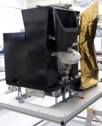
Figure 14: Picture and sketch of the sun baffle (image credit: CSL (Centre Spatial de Liège), Belgium)

Figure 15: Sketches extracted from the non-sequential ray-tracing software FRED (a) Earth illumination ray tracing. (b) Surfaces of the baffle visible from the diffuser (i.e. critical surfaces). (c) and (d): surfaces illuminated by the sun for configuration vSun2 and vAxis respectively (image credit: CSL)
A sun baffle has been designed, built and tested for the UVN embedded calibration assembly. The baffle has been designed to minimize the surfaces which are at the same time illuminated from the scene and seen from the detector. A straylight analysis has been performed with the non-sequential ray-tracing software FRED and a coating trade-off has led to the decision of using inorganic black anodization coating on the entire baffle except for a cone at the bottom of the baffle which is acktar coated. Experimental characterization has been performed in the clean room of the Space Center of Liège and confirms the straylight rejection performance of the system.
Sentinel-4 Ground Segment:
The Sentinel-4 Ground Segment elements are integrated and embedded within the EUMETSAT MTG ground segment. They comprise the following elements (Ref. 12):
1) The Sentinel-4 Level 1b and Level 2 processors
2) The generic and multi-mission supporting functions of the EUMETSAT MTG PDGS (Payload Data Ground Segment ) and FOS (Flight Operations Segment)
3) The Sentinel-4 ground segment system interfaces.
These ground segment interfaces are manifold at various levels:
- Sentinel-4 Payload (S4/UVN) to Sentinel-4 L1b Processors. This interface is part of the MTG Space-to-Ground Interface
- MTG Ground Segment to S4/UVN Level 2 Processor interface for non-S4 data required for processing
- Sentinel-4 User Interface like to i) the Copernicus User Community, ii) the Sentinel-4 Expert Users, iii) the Copernicus Space Component Coordinated Data Access System (CCS CDS)
- Sentinel-4 Level 2 Interface to ECMWF and other auxiliary providers (TBC)
- Sentinel-4 L1b Processor Interface to Sentinel-4 Image Quality Tool (IQT) which is part of the MTG-S IQT
- Interface with the ESA Sentinel-4 Mission Management. This interface is assumed to be a procedural interface.
Future coverage configuration scenarios with different missions (Ref. 10)
• Revisit time
- GEO (Geostationary Orbit): hourly ⇒ Several phases of diurnal cycle, ⇒ More clear sky observations / day
- LEO (Low Earth Orbit): daily at equator, several at high latitudes
• GAC (Geographic Coverage Area)
- GEO: Europe + part of Sahara + part of Atlantic
- LEO: global
• Target Species
- GEO: O3, NO2, HCHO, SO2, aerosol, (CHOCHO) ⇒ Air Quality
- LEO: CO, CH4, ....
• Target vertical range
- GEO: spectral range starts at 305 nm ⇒ tropospheric ozone
- LEO: stratospheric ozone profile.

Figure 16: GEO + LEO (image credit: ESA)

Figure 17: GEO + LEO (image credit: ESA)

Figure 18: GEO + GEO + GEO + LEO (image credit: ESA)

Figure 19: GEO + LEO (image credit: ESA)
1) G. Bazalgette Courrèges-Lacoste, M. Arcioni, Y. Meijer, J.-L. Bézy, P. Bensi, J. Langen, "Sentinel-4: The Geostationary Component of the GMES Atmospheric Monitoring Mission," Proceedings of the 7th ICSO (International Conference on Space Optics) 2008, Toulouse, France, Oct. 14-17, 2008
2) http://esamultimedia.esa.int/docs/S4-Data_Sheet.pdf
3) Mark R. Drinkwater, "ESA's Living Planet Programme: Atmosphere Explorer and Sentinel Missions," May 2010, URL: http://earth.eo.esa.int/workshops/Volcano/files/ESA_future_missions.pdf
4) Grégory Bazalgette Courrèges-Lacoste, Berit Ahlers, Benedikt Guldimann, Alex Short, Ben Veihelmann, Hendrik Stark, "The Sentinel-4/UVN instrument on-board MTG-S," URL: https://www.eumetsat.int/cs/idcplg?IdcService=GET_FILE&dDocName=pdf_conf_p59_s1_01_bazalget
_p&allowInterrupt=1&noSaveAs=1&RevisionSelectionMethod=LatestReleased
5) Hendrik R. Stark, Hermann Ludwig Möller, Grégory Bazalgette Courrèges-Lacoste, Rob Koopman, Silvia Mezzasoma, Ben Veihelmann, "The Sentinel-4 mission and its implementation," Proceedings of the ESA Living Planet Symposium, Edinburgh, UK, Sept. 9-13, 2013 (ESA SP-722, Dec. 2013)
6) Sentinel-4, ESA, Factsheet, URL: http://www.spaceoffice.nl/blobs/spaceplaza/files/s4data_sheet.pdf
7) "Copernicus: new name for European Earth Observation Programme," European Commission Press Release, Dec. 12, 2012, URL: http://europa.eu/rapid/press-release_IP-12-1345_en.htm
8) Paul Ingmann, Ben Veihelmann, Anne Grete Straume, Yasjka Meijer, "The status of implementation of the atmospheric composition related GMES missions Sentinel-4/Sentinel-5 and Sentinel-5p," Proceedings of the 2012 EUMETSAT Meteorological Satellite Conference, Sopot, Poland, Sept. 3-7, 2012, URL: http://tinyurl.com/oamraoh
9) "The EUMETSAT Council resolution approving the full Meteosat Third Generation (MTG) program entered into force on 25 February 2011," EUMETSAT Newsletter, May 12, 2011, URL: http://www.rational-systems.net/files/eum/devweb/v300/campaign_example_image-cover.html
10) Ben Veihelmann, Yasjka Meijer, Joerg Langen, Paul Ingmann, Rob Koopman, Norrie Wright, Gregory Bazalgette Courreges-Lacoste, Giorgio Bagnasco, "The Sentinel-4 Mission and its Atmospheric Composition Products," ATMOS Conference 2015, Heraklion, Crete, Greece, June 8-12, 2015, URL: http://seom.esa.int/atmos2015/files/presentation69.pdf
11) "Astrium to build ESA's Sentinel-4 atmospheric sensors," ESA, July 11, 2011, URL: http://www.esa.int/esaCP/SEMFSJ9TVPG_index_0.html
12) Hendrik R. Stark, Hermann Ludwig Möller, Grégory Bazalgette Courrèges-Lacoste, Rob Koopman, Silvia Mezzasoma, Ben Veihelmann, "The Sentinel-4 mission, its components and its implementation," Proceedings of the Joint EUMETSAT /AMS Meteorological Satellite Conference to address issues on Weather, Climate, Oceans and the Environment, Vienna, Austria, Sept. 16-20, 2013, URL: http://www.eumetsat.int/website/wcm/idc/idcplg?IdcService
=GET_FILE&dDocName-PDF_CONF_P_S1_10_STARK_V&Revision
SelectionMethod=LatestReleased&Rendition=Web
13) Heinrich Bovensmann, Stefan Noël, Klaus Bramstedt, John P. Burrows, R. Siddans, C. Standfuss, E. Dufour, B. Veihelmann, "Expected Level 2 Performance of Sentinel 4 UVN on MTG and the impact of scene inhomogeneity," ESA ATMOS (Atmospheric Science Conference) 2012, Bruges, Belgium, June 18-22, 2012, URL: http://congrexprojects.com/docs/12m06_docs2/8_bovensmann_public.pdf
14) Grégory Bazalgette Courrèges-Lacoste, Berit Ahlers, Benedikt Guldimann, Alex Short, Ben Veihelmann, Hendrik Stark, "The Sentinel-4/UVN instrument on-board MTG-S," EUMETSAT, URL: https://www.eumetsat.int/cs/idcplg?IdcService=GET_FILE&dDocName=pdf_conf_p59_s1_01_bazalget
_p&allowInterrupt-1&noSaveAs=1&RevisionSelectionMethod=LatestReleased
15) U. D. Zeitner, A. Kamm, T. Benkenstein, T. Flügel-Paul, G. Leibeling, "Development of the flight models for the Sentinel-4/UVN NIR-Grating Unit," Proceedings of the ICSO 2016 (International Conference on Space Optics), Biarritz, France, 18-21 October, 2016, URL: http://esaconferencebureau.com/custom/icso/2016/index.htm
16) L. Clermont, P. Blain, E. Mazy, J.Y. Plesseria, B. Marquet, Y. Stockman, "Design and tests of the sun baffle for the Sentinel-4 UVN embedded Calibration Assembly," Proceedings of the ICSO 2016 (International Conference on Space Optics), Biarritz, France, 18-21 October, 2016, URL: http://esaconferencebureau.com/custom/icso/2016/index.htm
The information compiled and edited in this article was provided by Herbert J. Kramer from his documentation of: "Observation of the Earth and Its Environment: Survey of Missions and Sensors" (Springer Verlag) as well as many other sources after the publication of the 4th edition in 2002. - Comments and corrections to this article are always welcome for further updates ().


