SOHO is an ESA/NASA collaborative mission within ESA's `Solar Terrestrial Science Program' (STSP), and it is also part of ISTP (International Solar Terrestrial Physics Program). So far, SOHO represents the most comprehensive space mission devoted to the study of the sun and of the heliosphere. Within the collaborative mission, the functions are divided in the following way: ESA is responsible for S/C procurement, integration and testing; NASA provided the spacecraft launch and mission operations from GSFC. The following overall mission objectives are pursued: 1) 2) 3) 4) 5) 6)
• Solar spectroscopy at soft X-ray and EUV wavelengths (study of the composition of the solar corona, of the structure and dynamics of the magnetic structures making up the corona, and of coronal holes, etc.)
• Study of the structure and dynamics of the solar interior through the observation of minute oscillations on the sun's surface (helio-seismology).
• Study of the solar wind and solar energetic particles, interaction with the Earth, plasma processes in both the solar and magnetospheric context.
History: SOHO was first proposed 13 years before its actual launch and the roots of SOHO were laid in earlier studies, namely those of GRIST (Grazing Incidence Solar Telescope) and DISCO (Dual Spectral Irradiance and Solar Constant Orbited). It is the combination of the objectives of these two missions that constitutes the core of the SOHO mission. 7)
In June 1976, GRIST had been competing with a 'Solar Probe' as well as other studies involving other disciplines for further study. Solar Probe envisaged a set of instruments on a spacecraft that would get close to the Sun. Although its assessment study cited four scientific disciplines interested in the mission, Solar Probe was not followed up at the time.
The GRIST study, on the other hand, proceeded to a feasibility stage. GRIST was preferred over Solar Probe because the wavelength range accessible through its optics was particularly useful for studying the hot outer solar atmosphere. GRIST was at that time being designed for flights on Spacelab.
Following the 1976 study, GRIST did not make it to project selection either. It was based on a collaboration with NASA which became a victim in 1981 of NASA's cancellation of the US probe in the International Solar Polar Mission (ISPM, the former 'Out-of-Ecliptic Mission', now called Ulysses). GRIST was 'parked', but restricted studies on its main spectrometers were supported by ESA.
In 1980, a group of French and American physicists observed the Sun continuously from Antarctica, studying solar physics with the best conditions available on Earth. These historic observations led to the decision to include the same sort of experiments on board a newly proposed mission called DISCO. DISCO would sit at the L1 Lagrange point between the Sun and Earth, which would be an ideal observing site. A miniaturized version of the South Pole experiment could be used as part of DISCO’s payload, provided its weight could be reduced.
DISCO was conceived as a fairly small and cheap spin-stabilized spacecraft, weighing no more than 520 kg. It was intended to prove that ESA could also undertake small and inexpensive missions. A first assessment was made in 1981, when DISCO had remained a relatively inexpensive spinning satellite, very similar to Cluster. ESA's Solar System Working Group preferred DISCO to a competing Mars mission called 'Keller', but DISCO eventually lost out to the Infrared Space Observatory in 1983.
SOHO itself developed as a mission in 1983, combining many of the aspects of the previously planned missions. It became important because it developed momentum, together with the Cluster mission, as part of the ISTP (International Solar–Terrestrial Physics) program. In May 1984, ESA identified SOHO as a part of the 'Cornerstone' of its long-term 'Horizon 2000' science program.
Partnerships: SOHO is part of the first Cornerstone project in ESA's Science program (the other is Cluster). Both are joint ESA/NASA projects in which ESA is the senior partner. SOHO and Cluster are also contributions to the ISTP program, to which ESA, NASA, Japan, Russia, Sweden and Denmark all contribute satellites monitoring the Sun and solar effects.
Of the spacecraft's 12 instruments, nine come from multinational teams led by European scientists, and three from US-led teams. More than 1500 scientists from around the world have been involved with the SOHO program.
SOHO was built by industrial companies in 14 European countries, led by Matra Marconi Space (now Astrium). The service module, with solar panels, thrusters, attitude control systems, communications, and housekeeping functions, was prepared in Toulouse, France. The payload module carrying the scientific instruments was assembled in Portsmouth, United Kingdom, and mated with the service module in Toulouse, France. NASA launched SOHO and is responsible for tracking, telemetry reception, and commanding (Ref. 7).
Figure 1: Overview of the main SOHO mission participants (image credit: ESA) 8)
Figure 2: SOHO image of the sun in the extreme ultraviolet range with the EIT instrument (image credit: ESA, NASA)
Figure 3: Schematic illustration of the deployed SOHO spacecraft (image credit: ESA)
Spacecraft:
The spacecraft was built by EADS-Astrium [formerly Matra Marconi Space (MMS)] as prime contractor. The SOHO spacecraft consists of two major elements, the Service Module (SVM) and the Payload Module (PLM). 9)
• SVM is a box-shaped structure made of aluminium honeycomb panels attached to a corrugated aluminium cylinder by four shear webs. The four lateral panels carry the data-handling, communication, attitude and orbit control, and power subsystems. The box's upper floor houses the propulsion subsystem, tank and thruster masts. The high-gain antenna is mated into the aft part of the central cylinder. The SVM with solar panels, thrusters, attitude control systems, communications and housekeeping functions, was prepared in Toulouse, France.
• PLM provides an optical bench for the experiments and is composed of four upper lateral panels and a top panel connected to a central cylinder by a number of shear webs. The bottom section, consisting of three lower lateral panels connected to the central cylindrical tube by a number of shear webs and floors, houses the PLM electronics. The PLM, carrying the scientific instruments, was assembled in Portsmouth, UK, and mated with the service module in Toulouse.
Figure 4: Artist's view of the deployed SOHO spacecraft (image credit: ESA)
SOHO has dimensions of 4.3 m x 2.7 m x 3.65 m (and 9.5 m span of the solar array).
AOCS (Attitude and Orbit Control Subsystem): The S/C is three-axis stabilized within 10 arcsec, with a sun-pointing stability of 1 arcsec over a period of 1.5 minutes. Actuators are 4 reaction wheels and two sets of eight thrusters. Attitude is measured by two fine-pointing sun sensors (FPSS), two star trackers also referred to as SSU (Star Sensor Unit), and three gyros. An SSU can track up to five stars. One of the stars is designated as guide star and is used as input for the control of the roll axis. When a single event upset occurs on the CCD inside or close to the guide star image the star data becomes unusable for control.
AAD (Attitude Anomaly Detector): The AOCS design is based on using independent hardware for anomaly detection and separate hardware for the safe mode. There is a pair of attitude anomaly detectors triggering when the sun off pointing is larger than 5º (Fine Sun Pointing Attitude Anomaly Detector, FSPAAD) and 25º (Coarse Sun Pointing Attitude Anomaly Detector, CSPAAD) respectively. These anomaly detectors are very simple (Figure 5). They consist of a cylinder with a hole at the top, internal baffles and a solar cell at the bottom (Ref. 36).
Figure 5: The FSPAAD (left) and CSPAAD (right), image credit: ESA
Power = 1500 W (solar cells) and 950 W from two 20 Ah NiCd batteries. The power bus is regulated to 28 V with a three-domain regulation of solar-array shunt mode, battery discharge and battery charge mode. S/C launch mass = 1850 kg, scientific payload mass = 650 kg, nominal lifetime = 3 years.
The data-handling central onboard software (in ADA) resides in a 16 bit computer (MAS 281) that uses the 1750A MIL-Standard instruction set and contains a set of programs controlling the data handling. It manages and distributes the onboard time, performs the thermal monitoring and thermal control of the satellite, manages the antenna pointing and monitoring, handles the inter-instrument data exchange, performs various other monitoring functions, and executes the initial sun-acquisition sequence. 10)
|
Spacecraft dimensions |
4.3 m x 2.7 m x 3.65 m (height, breadth, width) |
|
Length of solar array |
9.5 m |
|
Spacecraft mass at launch |
1850 kg |
|
Payload mass |
610 kg |
|
Spacecraft power |
1.5 kW |
|
Telemetry (real-time operations) |
200 kbit/s |
Table 1: Overview of some spacecraft parameters
Figure 6: The electrical architecture of the SOHO spacecraft
RF communications: Onboard solid-state recorder with 2 Gbit capacity. S-band data transmission (downlink frequency of 2.2-2.29 GHz, uplink of 2.025-2.110 GHz) with duplicated receivers and transmitters. RF coverage is provided by a pointable high-gain antenna (0.8 m dish) and two low-gain antennas, to ensure the full coverage. Housekeeping telemetry at 1 kbit/s, science data at 45 kbit/s, data dump (MDI, etc.) at 220 kbit/s.
The DSN (Deep Space Network) of NASA is providing TT&C support using existing ground station facilities at Madrid (Spain), Canberra (Australia) and Goldstone (CA, USA) and a central communications terminal at JPL. S/C operations are being performed by SMOCC (SOHO Mission Operations and Control Center) at NASA/GSFC. In addition, the SOHO POCC (Payload Operations Control Center) as well as other support functions are being performed at GSFC.
Figure 7: Two views of the SOHO spacecraft and its major components (image credit: ESA)
Launch: A NASA provided launch of the SOHO spacecraft took place from Cape Canaveral, FL, on December 2, 1995 aboard an ATLAS-II AS vehicle.
Orbit: Halo orbit around the Sun/Earth Lagrangian Point (L1), about 1.5 million km from Earth. In the Sun/Earth system, L1 is located on the sunward side of the Sun-Earth axis, where SOHO enjoys an uninterrupted view of the sun. The pointing accuracy of the S/C in the direction of the sun is better than 1 arcsec. SOHO was inserted into its halo orbit around L1 on Feb. 14, 1996 (six weeks ahead of schedule - it retained practically all of its hydrazine supply). Just like the Earth, SOHO takes a full year to orbit the sun. Its orbit affords SOHO an uninterrupted view of the sun, unlike satellites that orbit the Earth and periodically see the sun ”eclipsed” by the Earth.
Figure 8: Schematic view of the SOHO halo orbit about L1 (image credit: NASA) 11)
Status of the SOHO mission:
• The SOHO mission is operational as of January 2014. On Dec. 02, 2013, SOHO completed 18 years on-orbit. On 19 June 2013, the ESA Science Program Committee approved a new extension, until 31 December 2016, for SOHO, subjected to mid-term confirmation, in late 2014. 12)
• On January 13, 2014, ESA released a SOHO image entitled 'The abstract science of the dynamic Sun,' (Figure 9). The placid appearance of the Sun's surface belies a hot fireball of plasma in constant turmoil. A granular network invisible to the naked eye pervades the solar disc, with cells of hotter and colder plasma popping up, merging and disappearing within only a few hours. 13)
The boundaries between these constantly moving cells are hectic places. Powerful jets of plasma are often launched along the separation lines whenever the cell pattern changes, which may happen as a result of variations in the configuration of the magnetic field – known as ‘magnetic reconnection’.
To learn more about these reconnection jets and the energetic events that cause them, scientists observe the Sun at different wavelengths using a variety of techniques.
This image, which could be mistaken for a piece of abstract art, shows a series of observations performed with the ESA/NASA SOHO (Solar and Heliospheric Observatory) mission to study the evolution of reconnection jets on a small patch of the Sun’s surface.
The image shows 60 frames taken with the ultraviolet spectrometer SUMER on SOHO over 10 minutes. The individual frames were taken every 10 seconds, so each row of snapshots corresponds to almost three and a half minutes of observations.
Each frame shows a spectrum of the light coming from a small patch on the solar disc: the height of each frame measures 84,000 km, which is about a sixteenth of the Sun’s diameter.
The bright red and yellow regions in each frame correspond to boundaries between different cells in the granular pattern of the Sun. In the first few frames of the series, the shape of the central bright region is roughly vertical, a sign that the underlying boundary was in a quiet state.
After only a couple of minutes, however, the situation changed dramatically: towards the end of the first row and at the beginning of the second row, the shape of the bright region appears stretched towards the right. This shift is characteristic of a jet of plasma that is receding from the observed boundary at a speed of about 100 km/s.
The following snapshots report how the same boundary went back to a quiescent state, then underwent the launch of a new jet and became quiet once again. These rapid changes, and the powerful events causing them, indicate the highly dynamic nature of the Sun’s atmosphere.
The data shown in Figure 9 were collected on 28 March 1996 and this image was featured in the series of images “The Sun as Art” published on the SOHO website.

Figure 9: The abstract science of the dynamic Sun (image credit: ESA/NASA/SOHO/The SUMER team, Max Planck Institute for Solar System Research)
• Oct. 31, 2013: Several large, active regions on the Sun burst out with about 20 eruptions between 25 and 28 October 2013. Some were flares; some were coronal mass ejections, and at least one was a prominence eruption. 14)

Figure 10: Image of the solar corona acquired with LASCO's C2 coronagraph on Oct. 26, 2013 (image credit: ESA, NASA)
Legend to Figure 10: This is an image of the stormy Sun in extreme UV light from the Solar Dynamic Observatory superimposed on a visible-light image of the solar corona obtained with LASCO's C2 coronagraph of SOHO. The Sun is about at its maximum level of activity in its 11-year solar cycle, so stormy stretches like this one are to be expected.
• On July 18,2013, the SOHO spacecraft mission of ESA and NASA captured an image of a gigantic coronal hole hovering over the sun’s north pole (Figure 11). Coronal holes are dark, low density regions of the sun’s outermost atmosphere, the corona. They contain little solar material, have lower temperatures, and therefore, appear much darker than their surroundings. 15) 16)
Coronal holes are a typical feature on the sun, though they appear at different places and with more frequency at different times of the sun’s activity cycle. The activity cycle is currently ramping up toward what is known as solar maximum, predicted for late 2013. During this portion of the cycle, the number of coronal holes decreases. During solar max, the magnetic fields on the sun reverse and new coronal holes appear near the poles with the opposite magnetic alignment. The coronal holes then increase in size and number, extending further from the poles as the sun moves toward solar minimum again. At such times, coronal holes have appeared that are even larger than this one.
The holes are important to our understanding of space weather, as they are the source of a high-speed wind of solar particles that stream off the sun, some three times faster than the slower wind elsewhere. While it’s unclear what causes the coronal holes, they correlate to areas on the sun, where magnetic fields soar up and away, failing to loop back down to the surface, as they do elsewhere.

Figure 11: SOHO image of the sun with an extended coronal hole in the north pole region (image credit: ESA, NASA)
• Mission operations extension: On June 19, 2013, ESA's SPC (Science Program Committee) approved an extension of the SOHO mission until the end of 2016 - consistent with previous cycles, these are subject to mid-term confirmation, in late 2014. 17)
• On May 1, 2013, the the Sun blasted out a CME (Coronal Mass Ejection). In a gigantic rolling wave, this CME shot out about a billion tons of particles into space, traveling at over a 1.6 million km/hr. This CME is not headed toward Earth. 18)

Figure 12: Imagery from SDO, SOHO and its LASCO instrumentation of the May 1, 2013 coronal mass ejection (image credit: NASA/ESA)
Legend to Figure 12: This image shows three views of the CME from three different instruments. Left is the SDO (Solar Dynamics Observatory) image, taken at 02:40 UT. Center is from the SOHO spacecraft, looking through their coronograph instrument. The “mushroom” cloud of plasma leaving the Sun is visible. On the right is the LASCO C2 (red) and C3 (blue) instruments on SOHO, which use a disk to block out the Sun. Visible are the solid occulter disk, used to create a false eclipse; the “pylon”, which is an arm that holds the occulter disk in place; a representation of the Sun in the form of a white disk drawn on the occulter during the image processing and then one can see background stars and the cloud of plasma leaving the Sun (Ref. 18).
• In 2013, the SOHO mission is operational (the mission is extended to Dec. 31, 2014). 19) 20)
- ESA/NASA MOU (Memorandum of Understanding) to extend the mission to Dec. 31, 2016.
• In 2012, the SOHO mission is operational in its 17th year on orbit. The mission is extended to the end of 2014, subject to a mid-term review in 2012 (Ref. 22).
• On June 7, 2011, the Sun unleashed one of the most spectacular prominence eruptions ever observed. Based on real-time LASCO data, space weather forecasters could determine within hours that Earth would receive only a glancing blow from the associated CME (Coronal Mass Ejection), not a major space weather-induced event as hyped in the media. The event originated from the almost spotless active region 11226 and was associated with a moderate M2-class X-ray flare. The CME and associated shockwave produced an S1-class radiation storm, which shows up as speckles in the LASCO images. This event is not only one of the most spectacular ever recorded, but also one of the best observed, with complementary data from several spacecraft and different vantage points (SDO, SOHO, STEREO, PROBA-2). 21)
Figure 13: CME as recorded by SOHO’s LASCO instrument a few hours after the prominence eruption from the Sun’s surface on June 7, 2011 (image credit: NASA, ESA)
• The SOHO mission is operational in 2011. 22)
• On Dec. 2, 2010, the SOHO mission of ESA and NASA celebrated 15 years in orbit. During this time, SOHO has revolutionized what we know about the solar atmosphere and violent solar storms produced by the sun. 23)
• In November 2010, ESA's Science Program Committee (along with NASA) approved an extension of the SOHO mission for 4 years up to the end of 2014, subject to confirmation in late 2012 on the regular two-year cycle. The extension for SOHO will ensure that our Sun is closely watched during the rise to its next peak of magnetic activity, expected in 2013. 24)
• Since August 1, 2010, the EIT (Extreme-Ultraviolet Imaging Telescope) instrument has reverted back to its original observing mode, taking images of the Sun only twice per day. For almost 15 years, the EIT camera on board SOHO transmitted a picture of the solar corona every 12 minutes, providing ground-breaking observations of the Sun that changed our perception and understanding of our star. 25)
- This telescope was originally intended as a mere viewfinder, to set the context for data collected by the two spectrographs. As such, EIT was supposed to take images of the corona twice a day. Only after having seen the Sun with EIT did the project fully realize the enormous scientific potential of the instrument. This is why it was decided shortly after launch to increase the cadence of the snapshots to one every 12 minutes. EIT is probably SOHO's most popular workhorse, having taken over 500,000 snapshots of the Sun.
- EIT’s observations have strongly influenced the evolution of solar physics, paving the way for NASA's SDO (Solar Dynamics Observatory) mission, launched on Feb. 11, 2010. Thanks to substantial improvements in technology, the AIA (Atmospheric Imaging Assembly) instrument with an array of ultraviolet telescopes on board SDO is able to monitor the Sun at much higher cadence and at much greater resolution than SOHO's EIT. After a few months of joint operations to cross-calibrate the instruments, it was time for EIT to pass the baton to its successor (Ref. 25).
• The SOHO mission is operating nominally in 2010 (in its 15th year on orbit). On Oct. 7, 2009, ESA's Science Program Committee approved the extension of the SOHO mission operations to Dec. 31, 2012. This mission extension will enable to cover the totality of a solar cycle. 26) 27)
• The SDO (Solar Dynamics Observatory) of NASA was launched on Feb. 11, 2010. SDO is considered to be the next generation mission and successor to SOHO. It is expected that the SOHO mission will be continued at least as long until the SDO mission has become operational so that a period of cross calibration between the instruments of both spacecraft can be obtained.
• On Nov. 23, 2009, ESA's new SOHO science archive became online allowing for seamless access to the complete archive of science data sets from the 12 instruments as soon as the data are processed. The new facility improves access to SOHO data as it provides additional capabilities to search and visualize data. 28)
• On Dec. 2, 2007, SOHO completed its 12th year in orbit. The satellite has witnessed the sun change through almost a complete solar cycle - from quiet to stormy, and back again. The solar cycle normally lasts about 11 years. In late 1996, shortly after its launch, SOHO was able to observe the last minimum of the 11-year activity cycle. The minimum was followed by a rapid rise in solar activity, peaking 2001 and 2002. - Activity levels have slowly declined since then, but we haven't reached solar minimum yet, despite passing 11.1 years since the last minimum - the average length of a solar cycle. 29)
• Originally, SOHO was meant to operate only until 1998; but the mission was so successful that ESA and NASA decided to prolong its life until 2007 (the 1st mission extension was until 2003). This will allow SOHO to operate for a full 11 year solar cycle, from a minimum (a few dark sunspots) through a maximum to minimum again. A key objective of this SOHO Solar Cycle Mission is to better understand the cyclic activity of the sun, from changes in its interior through its atmosphere and out into interplanetary space.
• At the SPC (Science Program Committee) meeting in May 2006, a further extension of the SOHO mission was approved pushing back the mission end date from April 2007 to December 2009. 30)
• On Dec. 2, 2005, the SOHO spacecraft was 10 years on-orbit. 31) 32)
Since its launch on December 2, 1995, SOHO has revolutionized our understanding of the Sun. It has provided the first images of structures and flows below the Sun’s surface and of activity on the far side. SOHO has revealed the Sun’s extremely dynamic atmosphere, provided evidence for the transfer of magnetic energy from the surface to the outer solar atmosphere, the corona, through a ‘magnetic carpet’, and identified the source regions of the fast solar wind. It has revolutionized our understanding of solar-terrestrial relations and dramatically improved our space weather-forecasting by its continuous stream of images covering the atmosphere, extended corona and far side. The findings are documented in an impressive number of scientific publications: over 2500 papers in refereed journals since launch, representing the work of over 2300 individual scientists. At the same time, SOHO’s easily accessible, spectacular data and fundamental scientific results have captured the imagination of the space science community and the general public alike. As a byproduct of the efforts to provide real-time data to the public, amateurs now dominate SOHO’s discovery of over 1100 Sun-grazing comets.
• In May 2003, the SOHO team recorded signs of a possible breakdown in the east-west pointing mechanism of the high-gain antenna (HGA) [the Z-axis (azimuth) mechanism of the HGA is no longer working in the nominal operational mode]. The project feared that the mission was again in danger. After a long and careful analysis of all options, the team once more found a solution. The project decided to 'park' the antenna in an ideal position (where data losses are minimized), by rotating the spacecraft 180º every three months. In addition, the team established new procedures and the use of larger ground antennae (when available) to all but eliminate the impacts to normal science operations.
• SOHO mission recovery: Operational control of the SOHO S/C was lost on June 25, 1998 (when SOHO spun out of control and communication was lost). The first successful attempts to regain control were conducted on Sept. 16, 1998. The S/C was directed to turn its face and the solar power panels fully towards the sun (in addition, failure of three S/C gyros during the recovery period). Instrument re-commissioning started on Oct. 5, 1998 with SUMER and ended with CELIAS on Oct. 24, 1998. Final recovery from ESR (Emergency Sun Re-acquisition mode) and full S/C operation of SOHO was regained Feb. 1, 1999. A gyroless mode of operation was devised and installed with a new software patch for a modification of the AOCS (Attitude and Orbit Control Subsystem), making SOHO the first three-axis-stabilized S/C of ESA to be operated without a gyroscope. 33) 34) 35)
Prior to 1999, a gyro-based roll control mode was used when a SEU (Single Event Upset) occurred. Now the roll controller input is changed to one of the other stars still being tracked, taking into account the difference in position on the CCD between the original and the new guide star. With this new approach the spacecraft has survived all major solar flares during the last solar maximum without any fall backs to the new CRP (Coarse Roll Pointing) mode. This would have been very unlikely with the original design. 36)
The needed roll measurement in the new CRP mode is now implemented using the so-called CRS (Coarse Roll Sensor). It uses the on-board wheel momentum computed from the measured wheel speeds. The principle is illustrated in Figure 14 and is based on the conservation of angular momentum. Since the spacecraft rates around the pitch (Y) and yaw (Z) axes are being controlled to be zero using the FPSS, the spacecraft momentum in the transverse Y-Z plane is coming from the wheels. If the spacecraft is rotating slowly around the roll (X) axis then the transverse component of the inertial momentum vector will rotate in the opposite direction in the spacecraft Y-Z plane. By computing the component of the wheel momentum in the Y-Z plane from the measured wheel speeds and the known wheel inertia the evolution of the roll angle can be followed from the initial reference measurement (Ref. 36).
Before 1998 thruster maneuvers (station keeping and momentum management) were performed in a specific mode with the thrusters providing both attitude control and ΔV. The ΔV thruster pair (only use of the sunward and anti-sunward ΔV) was operated with off-modulation using a 75% duty cycle. The other thrusters were operated in on-modulation for attitude control. Momentum management was performed by commanding the wheels to their desired speeds using a simple wheel speed control loop and letting the thrusters counteract the attitude disturbances caused by the changing wheel momentum. Obviously this was not going to work without a gyro.
Now, the project uses a wheel based mode with the FPSS and SSU as sensors and command the thrusters in open loop using pulse trains with a very low duty cycle. The duty cycles are chosen such that the disturbance rates stay within the capability of the SSU. The SSU has a roll rate limit of 40 arcsec/sec. Also the pauses between the individual pulses have to be long enough for the controller to recover from the thruster pulse disturbance. For station keeping a duty cycle of approximately 5% is used with a pulse length of a little less than 1 sec and a period of 20 sec. For momentum management, an axis by axis approach is employed where a single thruster pulse train is fired causing a disturbance which is then counteracted by the wheel based control, driving the wheel speeds towards their targets. This is exactly the opposite from the pre-gyroless momentum management. Of course, the duration of the maneuvers is longer than before 1998 due to the low duty cycles. However when doing regular station keeping to maintain the semi-stable halo orbit, only a very small ΔV is required.
The total hydrazine fuel used during 2008 is less than 1 kg. The current (January 2009) fuel estimate is 118 kg of hydrazine (Ref. 36).
Figure 14: Illustration of the CRS principle (image credit: ESA, NASA)
Figure 15: SOHO solar array degradation based on the average of two section currents (image credit: ESA, Ref. 36)
• SOHO was launched in December 1995 by an Atlas Centaur rocket and became operational in March 1996.
Sensor complement: (SUMER, CDS, EIT, UVCS, LASCO, SWAN, CELIAS, COSTEP, ERNE, GOLF, VIRGO, MDI)
The scientific payload of SOHO comprises 12 complementary instruments, developed and furnished by 12 international consortia involving 29 institutes from 15 countries. Nine consortia are led by European scientists, the remaining three by US scientists. More than 1500 scientists in countries all around the world are either directly involved in SOHO's instruments or have used SOHO data in their research programmes. 37) 38) 39)
|
Instrument/Experiment |
PI (Principal Investigator) |
Objective |
|
Solar atmosphere remote sensing instrument package |
||
|
SUMER (Solar UV Measurement of Emitted Radiation) |
K. Wilhelm, MPAe, Lindau, Germany |
Plasma flows, temperature and density in the solar atmosphere |
|
CDS (Coronal Diagnostic Spectrometer) |
R. A. Harrison, RAL, Chilton, UK |
Density, temperature and flows in the solar atmosphere |
|
EIT (Extreme UV Imaging Telescope) |
J. P. Delaboudinière, IAS/CNRS, Orsay, France |
Evolution of low coronal structure and activity |
|
UVCS (UV Coronagraph and Spectrometer) |
J. L. Kohl, SAO, Cambridge, MA, USA |
Density and temperature in the corona |
|
LASCO (Large Angle Spectrometer Coronagraph) |
G. E. Brueckner, NRL, Washington DC, USA |
Structure and evolution of the corona |
|
SWAN (Solar Wind Anisotropies) |
J.-L. Bertaux, CNRS, Paris, France |
Solar wind mass flux anisotropies |
|
Solar wind “in situ particle” instrument package |
||
|
CELIAS (CHarge, Element, Isotope Analysis) |
D. Hovestadt, MPE, Garching, Germany |
Ion composition in the solar wind |
|
COSTEP (Suprathermal & Energetic Particle Analyzer) |
H. Kunow, University of Kiel, Kiel, Germany |
Ion and electron composition in the solar wind |
|
ERNE (Energetic and Relativistic Nuclei and Electron experiment) |
J. Torsti, University of Turku, Finland |
To detect charged particles in the solar atmosphere produced in various solar energy release processes |
|
Helio-seismology instrument package (study of the sun's interior) |
||
|
GOLF (Global Oscillations at Low Frequencies) |
A. Gabriel, IAS/CNRS, Orsay, France |
Global sun velocity and magnetic field oscillations |
|
VIRGO (Variability of Solar Irradiance) |
C. Fröhlich, WRC, Davos, Switzerland |
Global and low resolution imaging of oscillating and solar constant |
|
MDI (Michelson Doppler Imager) |
P. H. Scherrer, Stanford University, Stanford, CA, USA |
High resolution imaging of velocity oscillations |
Table 2: Overview of the SOHO sensor complement
Figure 16: Artist's rendition of the SOHO payload module (image credit: ESA)
Solar atmosphere remote sensing instrument package:
SUMER (Solar Ultraviolet Emitted Radiation):
SUMER PI: K. Wilhelm, MPAe, Katlenburg-Lindau, Germany (international cooperation of MPAe, IAS, NASA/GSFC, ETH Zürich, AIT Tübingen, PTB Berlin, SSL/UCB, ESA). Study of plasma flow characteristics (turbulent motions, waves. temperatures, and densities of the plasma in the upper atmosphere of the sun). SUMER consists of a UV telescope and a spectrometer, taking images of the sun in EUV (Extreme Ultraviolet) light with high resolution in space, wavelength and time. Note: In 2004 MPAe changed its name to MPS (Max Planck Institute for Solar Research).
The instrument characteristics are: 40)
• Single parabolic mirror telescope. Pointing and scanning is being performed by a mirror mechanism, which has a 2-D scan capability of ± 32 arcmin. One step is equivalent to 0.76 arcsec; half steps are possible. The east-west scan mechanism has to be operated in high-current mode (provided by the redundancy concept of SUMER) since autumn 1996. In order to maintain this capability, east-west raster scans are no longer permitted with SUMER. Pointing and rotation compensation procedures, however, can be employed without restrictions.
• Normal incidence spectrometer with the grating in a Wadsworth mount. Wavelength range: 500-1610 Å (or 50-161 nm). Scans can be performed within 21 s over the full range.
• Two 2-D microchannel plate detectors with cross delay-line anodes in photon-counting mode; KBr and bare microchannel plate photocathode.
• Spatial resolution: 1.2-1.5 arcsec; the pixel size corresponds to approximately 1 arcsec.
• Spectral resolution: lambda/delta lambda = 19,000 to 40,000, where delta lambda corresponds to the pixel size. Sub-pixel accuracy is achievable for the determination of line shifts and widths.
• Typical minimum sampling times: 3 to 10 s.
• Doppler velocities down to 1 km/s can be measured separately for each spatial resolution element.
• Rear slit camera for monitoring the slit position on the solar disk.
Data: on-line profiles, shifts and broadenings, ratios of temperature- and density-sensitive EUV emission lines in the range between 104 and 2 x 10⁶ K.
Figure 17: Photo of the SUMER instrument (image credit: MPS)
Figure 18: Optical design of the SUMER instrument (image credit: MPS)
CDS (Coronal Diagnostic Spectrometer):
CDS PIs: R. A. Harrison, A. Fludra, RAL, Chilton, UK. Study of the transition region and corona temperature and density (intensity ratios of selected EVU line pairs, with spatial and temporal scales appropriate to the fine-scale features of the solar atmosphere). There is close collaboration and correlation with SUMER. 41) 42) 43) 44) 45) 46) 47)
The instrument features a Wolter-Schwarzschild type II grazing incidence telescope [designed by MPE Garching, outer f-number = 9.48, focal length = 257.83 cm, FOV = 4 arcmin, on-axis resolution = 2 arcsec (FWHM)], a normal incidence spectrometer (NIS) with a wavelength = 2 bands in 240 - 800 Å range, and a grazing incidence spectrometer (GIS) with a wavelength = four bands in the 150 - 800 Å range.
Figure 19: The optical layout scheme of the CDS with normal and grazing incidence spectrometers (image credit: RAL)
Figure 20: The optical layout of CDS (image credit: RAL)
Figure 21: The optical bench of the CDS (image credit: RAL)
EIT (Extreme-Ultraviolet Imaging Telescope):
EIT PI: J. P. Delaboudinière, IAS (Institut d'Astrophysique Spatiale)/CNRS, France [international collaboration, NASA/GSFC, NRL, ROB (Royal Observatory), Belgium, IOTA, CSL, Belgium, LAS, France, etc.]. Study of the evolution of chromospheric and coronal structures (identification and interpretation of the spatial and temperature fine structures of the solar atmosphere). EIT provides full disk images in emission lines formed at temperatures that map the solar structures. Images in four narrow band passes are obtained using normal incidence multilayered optics deposited on the quadrants of a Ritchey-Chrétien telescope. Temperature range of solar structures to be measured: 6 x 10⁴ - 3 x 10⁶ K. Resolution = 1 arcsec (uniform over FOV = 50 x 50 arcmin). EIT is able to measure the solar transition region and inner corona in four, selected bandpasses in the extreme ultraviolet (EUV): 48)
|
Wavelength |
Ion |
Peak temperature |
Observational objective |
|
304 Å |
He II |
8.0 x 10⁴ K |
Chromospheric network, coronal holes |
|
171 Å |
Fe IX-X |
1.3 x 10⁶ K |
Corona7transition region boundary, structures inside coronal holes |
|
195 Å |
Fe XII |
1.6 x 10⁶ K |
Quiet corona outside coronal holes |
|
284 Å |
Fe XV |
2.0 x 10⁶ K |
Active region |
Table 3: Bandpasses of the EIT instrument
Using either full-disk or subfield images, the EIT can image active regions, filaments and prominences, coronal holes, coronal “bright points,” polar plumes, and a variety of other solar features. EIT was designed to be used in conjunction with other instruments, in particular LASCO, SUMER and CDS.
Figure 22: Illustration of the EIT instrument (LMSAL)
Figure 23: Schematic of EIT including its major subsystems (image credit: IAS)
|
Telescope |
Mirrors |
- Multilayer-coated Zerodur |
|
CCD detector (cooled to ~-80ºC) |
Architecture |
- Three-phase, multiphase pinned, back-illuminated,enhanced EUV sensitivity |
|
Filters |
Entrance filter |
- 1500 Å Al/700 Å cellulose/1500 Å Al |
|
Telemetry |
Normal average rate |
- 1 kbit/s |
Table 4: Overview of EIT instrument parameters
Figure 24: Image of the sun taken by the EIT instrument (image credit: NASA)
EIT is the first long-duration instrument to use normal incidence multilayer coated optics to image the sun in extreme ultraviolet. This portion of the spectrum is extremely difficult to reflect, as most matter absorbs the light very strongly. Conventionally these wavelengths have been reflected either using grazing incidence (as in a Wolter telescope for imaging X-rays) or a diffraction grating (as in the infamous overlappograph flown on Skylab in the mid-1970s.
UVCS (Ultra-Violet Coronograph Spectrometer):
UVCS PI: J. L. Kohl, SAO (Harvard-Smithsonian Astrophysical Observatory), Cambridge, MA, USA. Study of electron and ion temperatures, densities and velocities in the corona (for interpretation of coronal heating, solar wind acceleration, and solar wind composition). Spectroscopic measurements of the solar corona out to 10 solar radii from the sun's center (detailed description of the extended solar corona that can be used to address a broad range of scientific questions regarding the nature of the solar corona and the generation of the solar wind. 49) 50)
Figure 25: Schematic illustration of the UVCS instrument (image credit: SAO)
The UVCS instrument consists of an occulted telescope and a high resolution spectrometer assembly. Three off-axis paraboloidal mirrors focus co-registered images of the extended corona onto the three entrance slits of the spectrometer assembly. The spectrometer has three sections. One section is optimized for line profile measurements of H I Lyman-α; its wavelength range is 1148 - 1248 Å. Another section is optimized for line intensity measurements of O VI lambda 1032; it is also used to observe Si XII lambda 499 and 521 in second order. The first order range is 932 - 1068 Å. The Mg X doublet at lambda 610 and lambda 625 may be observed in first order. The third section is used to measure polarized radiance of the visible corona.
Telescope: off-axis parabolic mirror, focal length = 750 mm, image scale = 0.218 mm/arcmin, FOV = 42' (tangential) x 141'.
Spectrometer: gratings = 105 (disp) x 70 mm; nominal radius = 750 mm; radius ratio = 1.0259 (1216 Å), = 1.0215 (1032 Å, 625Å), = 1.0040 (visible); ruling frequency = 2400 mm-1; reciprocal dispersion = 5.63 Å/mm (1st order), = 2.82 Å/mm (2nd order).
|
Spectral Line |
Observed Quantity |
Spectral Resolution |
Spatial Resolution |
|
H I 1216 |
Profile |
0.2 |
10” x 10” |
|
H I 1216 |
e- Profile |
2.0 |
1.6' x 1' |
|
Fe XII 1242 |
Intensity |
1.23 |
1' x 1' |
|
Fe XII 1242 |
Profile |
0.14 |
10” x 5' |
|
O VI 1032/37 |
Intensity |
1.23 |
1' x 1' |
|
O VI 1032 |
Profile |
0.14 |
10” x 5' |
|
Si XII 499/521, 2nd order |
Intensity |
0.61 |
1' x 1' |
|
Si XII 499, 2nd order |
Profile |
0.07 |
7” x 5' |
|
Mg X 610/625, 2nd order |
Intensity |
0.61 |
1' x 2.5' |
|
MG X 610, 2nd order |
Profile |
0.07 |
7” x 5' |
Table 5: Observational parameter specifications for the UVCS instrument
Figure 26: Photo of the UVCS instrument (image credit: SAO)
LASCO (Large-Angle and Spectrometric Coronograph):
LASCO PI: G. E. Brueckner, NRL, Washington DC, USA. LASCO was jointly developed by NRL, MPS, Katlenburg-Lindau, Germany, the LAS/CNRS (Laboratoire d'Astronomie Spatiale), Marseille, France, and the University of Birmingham, Birmingham, UK. Objectives: Study of structure evolution, mass, momentum and energy transport in the corona. Measurement of electron column densities from just above the limb, at 1.1 Rsun (solar radii - the solar radius is about 700,000 km), out into deep heliospheric space, at 30 Rsun. Spectral analysis of the inner corona with a high resolution scanning. imaging interferometer. Measurement of spectral profiles of three emission lines and one Fraunhofer line for each pixel (providing temperatures, velocities, turbulent motions and volume densities). Direction of coronal magnetic fields via polarization analysis. The LASCO instrument consists of the coronograph optical system (with three optical systems and CCD cameras) and the instrument control system. 51) 52)
LASCO takes white light and spectral images of the corona by blocking light from the sun with an occulting disk, mimicking an eclipse. The three telescopes, comprising LASCO, are designated: C1 (Coronagraph 1), with coverage from 1.1 to 3.0 Rsun, C2, with coverage deliberately overlapping parts of both C1 and C3, and extending from 2.0 to 6.0 Rsun, and the C3, which spans the outer corona from about 3.7 to 32 Rsun.
The inner corona instrument, C1, is a newly developed mirror version of the classic Lyot internally occulted coronagraph (Bernhard Lyot, 1897-1952, French astronomer, inventor of the coronagraph in 1930), while the C2 and C3 are externally occulted instruments. In addition, the C1 is fitted with an imaging Fabry-Perot interferometer, making possible spatially resolved high-resolution coronal spectroscopy in selected spectral emission and absorption lines, between 1.1 and 3.0 Rsun. High definition CCD cameras in each telescope provide detailed images with exceptional dynamic range, while large digital memories and a high-speed microprocessor support extensive onboard image processing and image data compression by large factors, that allow transmission of up to 10 full coronal images per hour.
Figure 27: The LASCO instrument (image credit: NRL)
|
Telescope |
FOV R/Rsun |
Occulter type |
Spectral bandpass |
Objective element |
CCD array (pixels) |
Pixel size |
Brightness temperature range (TB) |
|
C1 |
1.1-3.0 |
Internal |
Fabry-Perot |
Mirror |
1024 x 1024 |
5.6 arcsec |
2x10⁻⁵-2x10⁻⁸ |
|
C2 |
2.0-6.0 |
External |
Broadband |
Lens |
1024 x 1024 |
11.4 arcsec |
2x10⁻⁷-5x10⁻¹⁰ |
|
C3 |
3.7-32 |
External |
Broadband |
Lens |
1024 x 1024 |
56.0 arcsec |
3x10⁻⁹-1x10-11 |
Table 6: Optical characteristics of the three coronagraphs of LASCO
SWAN (Solar Wind Anisotropies):
SWAN PI: J. L. Bertaux, CNRS, France). SWAN is a collaboration between Finnish Meteorological Institute (FMI) and Service d'Aeronomie (SA). Study of solar wind mass flux anisotropies and temporal variations. The SWAN instrument is a Lyman photometer which maps the sky's interplanetary hydrogen emission almost entirely every other day. From these sky maps, the latitude distribution of the solar wind mass flux from the equator to the pole can be measured, as well as the variation of this distribution (time scale≈one month). - SWAN is the only remote sensing instrument on SOHO that does not look at the sun. It watches the rest of the sky, measuring hydrogen that is 'blowing' into the solar system from interstellar space. By studying the interaction between the solar wind and this hydrogen gas, SWAN determines how the solar wind is distributed. As such, it can be qualified as SOHO's solar wind 'mapper'. 53) 54)
The instrument consists of two identical sensor units placed on opposite sides of the S/C and driven by a common electronic box. Each sensor consists of a two-mirror scanning system, a light baffle (to keep out stray light), a hydrogen cell in which a tungsten filament is alternately heated to produce Lyman-alpha absorbing hydrogen atoms and cooled to produce the reference signal. Resolution of the Lyman-alpha light distribution is 1º.
Figure 28: Illustration of the SWAN instrument (image credit: VTT)
Figure 29: SWAN optical configuration of one sensor unit (image credit: FMI)
|
Total instrument mass, electronic unit mass |
13.25 kg, 2.82 kg |
|
Mass of one sensor unit |
4.815 kg |
|
Average power consumption |
11 W |
|
Source data rate |
200 bit/s |
|
Total FOV (Field of View) |
> 2π sr for each sensor unit (2 mirror periscope) |
|
IFOV (Instantaneous Field of View) |
25 pixels of 1º x 1º = 5º x 5º |
|
Wavelength range |
115-180 nm |
|
Photometric sensitivity |
0.75 counts /s /Rayleigh /1º pixel |
|
Type of detector |
Solar blind MgF2 / CsI Cathode - Multi-anode MCP |
|
Count rate |
From 200/s (IP) to 104 /s (solar corona) per pixel |
|
Relative accuracy |
Better than 1% for 45 s counting time on IP signal |
|
Absolute accuracy |
Checked at regular time intervals with stellar calibrations |
|
Hydrogen cell |
Pyrex vessel (MgF2 lens windows-distance 76 mm) |
Table 7: SWAN instrument characteristics
Solar wind “in situ particle” instrument package
CELIAS (Charge, Element and Isotope Analysis):
CELIAS PI: D. Hovestadt, MPE, Garching, Germany, Universität Bern, Switzerland. Study of ionic energy distribution and composition of the solar wind. Measurement of the mass, ionic charge and energy of the low and high speed solar wind, of suprathermal ions, and of low energy flare particles. 55) 56) 57) 58)
|
Sensor |
Area, Geometric Factor |
ΔE/E |
Efficiency of the TOF unit |
|
CTOF (Charge Time-of-Flight) |
0.08 cm2 |
0.04 |
0.25 - 0.65 |
|
MTOF (Mass Time-of-Flight) |
0.013 cm2 |
0.03-5 |
0.03 - 0.1 |
|
PM (Proton Monitor) |
7 x 10⁻⁵ cm2 |
0.05 |
- |
|
STOF (Suprathermal Time-of-Flight) |
0.1 - 0.2 cm2 sr |
0.1 |
0.2 - 0.8 |
Table 8: Measurement capabilities of the CELIAS instrument
CELIAS includes three mass- and charge-discriminating sensors based on the time-of-flight technique: CTOF (Charge Time-of-Flight) for the elemental, charge and velocity distribution of the solar wind; MTOF (Mass Time-of-Flight) for the elemental and isotopic composition of the solar wind, MTOF also includes a proton monitor (PM); and STOF (Suprathermal Time-of-Flight) for the mass, charge and energy distribution of suprathermal ions. Mass resolution: M/ΔM > 100 MTOF; charge resolution: ΔQ ≈0.3 - 1, 4 <M<60 (typical for CTOF and STOF)].
In addition there is SEM (Solar EUV Monitor), a highly stable photodiode spectrometer which measures the full solar disk absolute photon flux at the prominent and scientifically important He II 30.4 nm line, as well as the absolute integral flux between 17 and 70 nm.
Figure 30: Illustration of the CTOF sensor of the CELIAS instrument (image credit: University of Bern)
Figure 31: View of the MTOF sensor of CELIAS (image credit: University of Bern)
Figure 32: View of the STOF sensor of CELIAS (image credit: University of Bern)
Figure 33: View of the SEM sensor of CELIAS (image credit: University of Bern)
COSTEP (Comprehensive Suprathermal and Energetic Particle Analyzer):
COSTEP PI: H. Kunow, University of Kiel, Germany. The science objectives of COSTEP are related to the study of: a) steady state processes in the solar atmosphere, b) energy release and particle acceleration in the solar atmosphere, c) samples of solar atmospheric material, and d) interplanetary medium. COSTEP consists of two instrument units: EPHIN and LION. 59) 60)
• EPHIN (Electron Proton Helium Instrument), a newly developed telescope for the measurement of energy spectra. The EPHIN sensor is a multi-element array of solid state detectors with anticoincidence to measure energy spectra of electrons in the range 250 keV to > 8.7 MeV, and of hydrogen and helium isotopes in the range 4 MeV/n to > 53 MeV/n.
• LION (Low Energy Ions and Electrons). The LION device is a stack of semiconductor detectors to measure energetic particles. The instrument consists of two sensor heads, each containing a double telescope, which together provide the capability to measure particle spectra in the range 44 keV to 6 MeV for protons and 44 keV to 300 keV for electrons. A channel for Z>1 particles, mainly alphas in the range 7-26 MeV, is also provided. 61)
Figure 34: Illustration of EPHIN (left) and LION units of COSTEP (image credit: University of Kiel)
ERNE (Energetic and Relativistic Nuclei and Electron):
ERNE PI: J. Torsti of the University of Turku, Finland. The objective is to detect charged particles in the solar atmosphere produced in various solar energy release processes. The instrument, ERNE Sensor Unit (ESU), consists of two energetic particle sensors: LED (Low Energy Detector) and HED (High Energy Detector), and an all analog and digital electronics as well as the Data Processing Unit (ESU-DPU) of these sensors are within this unit. 62) 63) 64)
Figure 35: Illustration of the ERNE instrument (image credit: University of Turku)
The specific ERNE objects consists of:
• Energy spectra of ions and electrons above 1 MeV/nucleon
• Elemental and isotopic abundance H to Fe
• Particle acceleration in the solar atmosphere and interplanetary shocks
• Particle propagation in the solar corona and in the interplanetary space
• Study both large and small scale properties of the IMF
• Short-period temporal variations of particle flux
• Flux anisotropy within the apparatus viewing cone
• Flux of protons penetrating the instrument (even decay solar neutrons).
ERNE measurements represent the first systematic survey of SEP (Solar Energetic Particle) isotopic abundance, with high sensitivity, high resolution sensors which cover a broad energy range.
The combined COSTEP and the ERNE instruments result in the so-called CEPAC (COSTEP-ERNE Particle Analyzer Collaboration) experiment aboard SOHO. CEPAC address a wide range of scientific topics including:
1) Energy releases and particle acceleration in the solar atmosphere (long duration events, impulsive events, non-flare associated particle events
2) Analysis of samples of solar atmospheric material (large solar particle events, elemental abundances, isotopic abundances, small 3He rich flares, impulsive kilovolt electron events);
3) Steady state processes in the solar atmosphere
4) Particle propagation in the interplanetary medium (travelling shock events, co-rotating interaction regions, small scale plasma events).
Helio-seismology instrument package (study of the sun's interior)
GOLF (Global Oscillations at Low Frequencies):
GOLF PI: A. Gabriel, IAS/CNRS, France. Study of the internal structure of the sun by measuring the spectrum of free global oscillations [global velocity and magnetic field oscillations (low degree modes)]. GOLF measures both p and g mode oscillations, with the emphasis on the low order long period waves which penetrate the solar core (frequencies between 10-7 and 6 x 10⁻² Hz, with a sensitivity of 1 mm/s). The method involves an extension to space of the ground-based technique for measuring the mean line-of-sight velocity of the viewed solar surface. A sodium vapor resonance scattering filter is used in a longitudinal magnetic field to sample the two wings of the solar absorption line. 65) 66)
Figure 36: Illustration of the GOLF instrument assembly (image credit: IAS)
Light from the sun passes through a filter which isolates a 17 Å band centered on the Na D lines. It is then brought to a focus by the lens L1 (see Figure 37). Lens L2 serves to produce a near parallel beam to traverse the vapor cell, while at the same time imaging the entrance pupil of the system at the center of the cell. After traversing the cell, the beam is effectively absorbed in a light trap. Light scattered from the vapor in the cell at 90º is collected by two photomultiplier tubes in a symmetrically opposed configuration, operating in photon counting mode. The cell is placed between the poles of a permanent magnet, giving a 5000 gauss longitudinal magnetic field through the sodium vapor. An additional longitudinal field of ± 100 gauss is applied by means of the small coils. The incident light is circularly polarized by a combination of the linear polarizer P1 and the quarter-wave plate QP2. A change of relative orientation of P1 and QP2 by 90º results in a change in the sense of the circularly polarized light transmitted. This change provides the measurement of the intensity ratio in the above equation, which is the direct indicator of the solar velocity vector. The addition of the second quarter-wave plate QP1 facilitates the measurement of the longitudinal component of the average solar magnetic field.
Figure 37: Schematic of measurement configuration of GOLF (image credit: IAS)
VIRGO (Variability of Solar Irradiance and Gravity Oscillations):
VIRGO PI: C. Froehlich, WRC (World Radiation Center), Davos, Switzerland; ESA/ESTEC. Study of irradiance oscillations (low degree modes) and the solar constant. The total irradiance is measured with active cavity radiometers PMO6-V and DIARAD (Differential Absolute Radiometer), the spectral irradiance by three-channel Sunphotometers (SPM), and the radiance with 12 resolution elements on the solar disk using LOI (Luminosity Oscillations Imager). A scientific objective is probing the solar interior by helioseismology with p- and g-mode solar oscillations determined from spectral irradiance (SPM) and radiance (LOI) variations to the mission time on time scales of minutes. 67) 68) 69) 70)
VIRGO consists of a number of subunits. The optical system of the VIRGO assembly consists of a Ritchey-Chrétien type telescope with a 1300 mm focal length, diameter of 55 mm, and central obstruction 25 mm. Detector: Deep diffused silicon photodiode with 12 scientific and 4 guiding pixels.
• PMO6-V (Physikalisch-Meteorologisches Observatorium, 6th radiometer - VIRGO), built by WRC of Davos, is an active cavity radiometer (absolute instrument) measuring continuously the degradation of the active instrument. Some parameter specifications are: life variation: 30 ppm/year, absolute accuracy: 0.17%, sampling rate: 1 solar total irradiance/2 minutes, duty cycle: 17%, resolution: 50 ppm.
• DIARAD (Differential Absolute Radiometer), built by IRMB, Brussels. An active cavity radiometer. It is composed of two cylindrical cavities coated inside with diffuse black and mounted next to each other on the same heat sink. Some parameter specifications are: lifetime variation: 30 ppm/year, absolute calibration: 0.15%, sampling rate: 1 solar total irradiance/3 minutes, duty cycle: 11%.
• SPM (Sunphotometer), built by WRC. There are two instruments to measure to measure the spectral irradiance at 335, 500, and 865 nm with a bandwidth of 5 nm.
• LOI (Luminosity Oscillations Imager), built by ESA. Measurement of the sun diameter variations with a precision of about 0.3 arcseconds for a 1.5 hour integration time. The LOI wavelength and bandpass is chosen to be the same as the 500 nm channel of SPM. This allows the instruments to be calibrated to each other.
The Total Solar Irradiance (TSI) is being observed with active cavity radiometers (PMO6 and DIARAD) which are traceable to the SI scale of irradiance through direct comparison with cryogenic radiometers on the ground and in vacuum for the PMO6, and thorough characterization in the laboratory for the DIARAD. SSI (Spectral Solar Irradiance) are carried out by SPM (Sunphotometers). - Over the long time period of SOHO mission observations, the VIRGO measurements indicate, that TSI is being increased by 0.1% at solar maximum as compared to the average values at solar minimum periods.
Figure 38: TSI monitoring results of various instruments in the period 1978 to 2000 (image credit: ESA, Ref. 75)
MDI (Michelson Doppler Imager):
MDI PI: P. H. Scherrer, Stanford University, Stanford, CA, USA). The key objective is the Solar Oscillations Investigation (SOI), an international project to study the interior structure and dynamics (velocity oscillations) of the sun's surface. The surface oscillations are an indication of the sun's interior behavior. Measurement of line-of-sight velocity by Doppler shift, transverse velocity by local correlation tracking, line and continuum intensity, and line-of-sight magnetic fields with both 4 and 1.4 arcsec resolution (2 and 0.7 arcsec pixels, respectively).
MDI provides velocity maps by sampling the solar Ni I 6768 Å line profile at four points and finding the Doppler shift by determining the phase of the first Fourier coefficient of the line shape with respect to a reference wavelength. 71) 72) 73)
Figure 39: Schematic of the MDI optical layout (image credit: Stanford University)
The MDI takes advantage of the Doppler effect, which shifts the sun's light to shorter wavelengths (making it appear more blue) when oscillating material moves toward SOHO and to longer wavelengths (red) when it is moving away. The oscillations on the sun are created by sound waves that bounce around within the sun, making it reverberate like a ringing bell. The effects of the sun's magnetic field are traced by observing it in different colors or wavelengths that reflect different temperatures. The magnetic field at the surface of the sun can be measured by looking at the sun with polarized filters that are tuned to very narrow spectral pass bands (color ranges).
Figure 40: Illustration of the MDI instrument (image credit: Stanford University)
SOHO Data: On-board recording capability of 1 Gbit of data (requirement of 48 h autonomous operation without ground contact)on a tape recorder and 2 Gbit in solid-state memory. Science data transmission via S-band (2.245 GHz). Downlink date rate at 40 kbit/s (160 kbit/s when MDI is in high rate mode).
Some achievements of SOHO observations
Since SOHO began its mission in 1995, the observatory has provided an unparalleled wealth of information about the sun, from its interior, through the hot and dynamic atmosphere, out to the solar wind. Only a few items are listed here. 74) 75) 76)
• Global structure and dynamics of the solar interior: The unprecedented accuracy of helioseismic data from SOHO's MDI, GOLF and VIRGO instruments has enabled substantial improvement in models of the solar interior, and has even shown the importance of considering mixing effects, who in turn solve existing riddles in the isotopic composition of the sun.
• Transition-region dynamics: Several types of transient events have been detected in the quiet sun. Explosive events have been studied using SUMER instrument data.
• Corona: LASCO and EIT are principal instruments. These instruments observed coronal mass ejections (CMEs) that generated subsequent disturbances (the first ever images of the turbulent outer shell of the sun and of the structure below sunspots). These disturbances were observed by other spacecraft to establish the cause-and-effect relationship for a solar system event that extended from the sun to the solar wind to Earth's magnetosphere and ionosphere. EIT has discovered large-scale transient waves (Coronal Moreton Waves) in the corona that propagate outward from the active regions below CMEs.
• Solar wind: The first tracing of the slow-speed solar wind near the equatorial current sheet
• Solar wind composition: The first detection of elements and isotopes in the solar wind (composition of calcium and nitrogen) observed from data of the CELIAS/MTOF instruments
• The first image of the convection zone of a star
• Monitoring the total solar irradiance (the 'solar constant') as well as variations in the extreme ultra violet flux, both of which are important to understand the impact of solar variability on Earth's climate.
• Revolutionizing our ability to forecast space weather, by giving up to three days notice of Earth-directed disturbances, and playing a lead role in the early warning system for space weather.
• One of the most surprising discoveries in the last years that regard the sun is that our star ”sings”. The notes, whose frequencies are too low to be heard by the human ear, cannot propagate in interplanetary space. The solar physics specialists, however, succeed to reveal a rhythmic movement produced at the surface of the sun, generated by the reverberation of the sound waves within. The consequent oscillations have precise frequencies, just like musical notes, and their analysis casts new light on the structure of the sun.
• The SOHO instruments MDI, SWAN, and LASCO have demonstrated the ability to track active regions across the invisible disk in new ways, benefiting forecasters and users of space weather information. SWAN can indirectly monitor the activity on the far side of the sun as it maps the whole sky in ultraviolet light. A huge cloud of interstellar hydrogen that bathes the entire solar system interacts with the solar wind, and lights up in the Lyman-alpha spectral line when it is hit by UV radiation from the sun. Since active regions on the sun are brighter in Lyman-alpha light, the part of the sky facing an active region is brighter.
The scientific achievements of the continuing SOHO mission are the result of a concerted, multi-disciplinary effort by a large international community of solar scientists. The analysis of the SOHO data has revolutionized the way scientists think about the sun and how it might affect the Earth's environment.
As of 2006, more than 2500 papers, representing the work of more than 2300 scientists, have been published based on SOHO data. With SOHO still going strong, the success story is set to continue.
Figure 41: A complete solar cycle has been imaged by the SOHO spacecraft (composite image credit: SOHO EIT consortium, ESA, NASA) 77)
SOHO the comet hunter:
Besides watching the sun, the instruments on SOHO are very prolific comet hunters - a byproduct of the SOHO information on internet and the painstaking search by a large community of interested people. The imagery of NRL's LASCO instrument is the most suitable for this purpose. Most of the comets have been found by amateur astronomers coming from all over the world and using the SOHO near-real-time imagery on the internet. 78)
- On Feb. 4, 2000, SOHO discovered its 100th comet.
- On Aug. 25, 2000, astronomers announced that SOHO had recorded its 200th sun-grazing comet
- As of May 2003, more than 620 comets had been found by the SOHO spacecraft.
- On June 11, 2004, 800 comets were discovered by SOHO instruments.
- In July 2005, ESA announced that 989 comets have been discovered by SOHO. So far, the SOHO spacecraft has accounted for almost half of all comet discoveries for which orbits have been computed in the history of astronomy.
- On Aug. 5, 2005, SOHO achieved an incredible milestone - the discovery of its 1000th comet! The 1000th comet was a Kreutz-group comet spotted in images from the C3 coronagraph on SOHO's LASCO instrument by Toni Scarmato, from Calabria, Italy.
- Also in 2005, the LASCO imagery revealed for the first time a rare type of comet called a periodic comet (which flies by the sun at regular intervals). While many SOHO comets are believed to be periodic, this is the first one that has been conclusively proven and officially declared as such.
Astronomers have seen thousands of comets but classified only around 190 as periodic. Many more are proposed to be periodic, but they only gain this classification officially if they are seen to follow their orbits around the sun more than twice, and have orbital periods of less than two hundred years. The most famous periodic comet is Halley's comet, returning every 76 years, with its last close pass to the sun taking place in 1986.
SOHO's new catch has a much smaller orbit, taking approximately four years to travel once around the Sun. It was first seen in September 1999, and then again in September 2003. In 2005, German PhD student Sebastian Hoenig realized that the two comets were so similar in orbit that they might actually be the same object. 79)
- About 85% of the SOHO comets discovered so far belong to the Kreutz group of ”sungrazing” comets, so named because their orbits take them very close to the sun. The Kreutz sungrazers come within 800,000 km of the sun's visible surface.
- As of May 2006, over 1100 sun-grazing comets have been discovered from SOHO data.
- As of Oct. 11, 2007 the SOHO comet count reached 1373.
- As of June 25, 2008, the SOHO comet count is 1500. 80)
- In February 2010, the SOHO comet count is 1683. 81)
- On December 26, 2010, the SOHO comet hunt reached 2000. 82)
Comet ISON (C/2012 S1) was discovered on Sept. 21, 2012 by Vitali Nevski and Artyom Novichonok of Russia (using a telescope). C/2012 S1 will come to perihelion (closest approach to the sun) on 28 November 2013 at a distance of 0.012 AU (~1.1 million km above the solar surface), classifying it as a sungrazing comet. There exists a potential for comet ISON to be one of the brightest comets of the past century. NASA foormed a team of experts to coordinate an observing campaign for this comet, under the assumption that it will become easily-visible by the latter part of 2013. 83)
Figure 42: SOHO's 2000th comet (left), spotted by a Polish amateur astronomer on December 26, 2010 (image credit: NASA)
1) P. Lo Galbo, M. Bouffard, “SOHO - A Cooperative Scientific Mission to the Sun,” ESA Bulletin, Aug. 1992, pp. 21-25
2) “The Solar-Terrestrial Science Project of the Inter-Agency Consultative Group for Space Science,” ESA SP-1107, November 1990, pp. 21-24
3) J. Credland, F. Felici, M. Grensemann, J. A. Steinz, “Three Missions, Three Launches, Six Spacecraft for Science in 1995,” ESA-Bulletin, No. 82, May 1995, pp. 36-47, URL: undefined
4) K. R. Lang, “SOHO Reveals the Secrets of the Sun,” Scientific American, in “Magnificent Cosmos,” Vol. 9, No 1, Spring 1998, pp. 50-55
6) SOHO brochure, ESA, URL: undefined
7) SOHO Overview, last update: April 12, 2012, ESA, URL: undefined
8) F. Felici, O. Meert, “The SOHO Project: An International Challenge,” ESA Bulletin No. 84, Nov. 1995,, URL: undefined
9) F. C. Vandenbussche, “The SOHO Spacecraft,” ESA Bulletin No. 84, Nov. 1995, pp. 87-91, URL: undefined
10) F. C. Vandenbussche, P. Temporelli, “SOHO - The Trip to the L1 Halo Orbit ,” ESA Bulletin, No 88, Nov. 1996, URL: undefined
12) “ESA science missions continue in overtime,” ESA, June 20, 2013, URL: undefined
13) “The abstract science of the dynamic Sun,” ESA, January 13, 2014, URL: undefined
14) “Our Stormy Sun,” ESA, Oct. 31, 2013, URL: undefined
15) Karen C. Fox, “Large Coronal Hole Near the Sun’s North Pole,” NASA, July 19, 2013, URL: undefined
16) “Large Coronal Holes,” ESA, July 19, 2013, URL: undefined
17) “ESA Science Missions continue in overtime,” ESA, June 20, 2013, URL: undefined
18) Nany Atkinson, “The Sun Burps Out a Gigantic Rolling Wave,” Universe Today, May 1, 2013, URL: undefined
19) SOHO - Science and Technology,” ESA, Feb. 24, 2013, URL: undefined
21) “Programmes in Progress: SOHO, Status end of July 2011, “ ESA Bulletin No. 147, August, 2011, p. 66
23) “Solar Observation Mission Celebrates 15 Years,” Space Daily, Dec. 6, 2010, URL: undefined
24) “Europe maintains its presence on the final frontier,” Nov. 22, 2010, URL: undefined
25) “A change of pace for EIT, the ground-breaking Sun-watching camera,” ESA, Sept. 21, 2010, URL: undefined
26) “Mission extensions approved for science missions,” ESA, Oct. 7, 2009, URL: undefined
28) “ESA's new SOHO science archive now online,” ESA, Nov. 23, 2009, URL: undefined
29) “SOHO - keeping an eye on the Sun for 12 years,” Dec. 4, 2007, URL: undefined
31) Bernhard Fleck, Daniel Müller, Stein Haugan, Luis Sánchez Duarte, Tero Siili, Joseph B. Gurman, “10 Years of SOHO,” ESA Bulletin No 126, May 2006, pp. 24-32, URL: undefined
32) “10 Years of SOHO,” Dec. 2, 2005, URL: undefined
33) F. C. Vandenbussche, “SOHO's Recovery - An Unprecedented Success Story,” ESA Bulletin No 97, March 1999, URL: undefined
34) Craig E. Roberts, “The SOHO Mission L1 Halo Orbit Recovery From the Attitude Control Anomalies of 1998,” Libration Point Orbits and Applications Conference, Parador d’Aiguablava, Girona, Spain, June 10-14, 2002, URL: undefined
35) “The SOHO Recovery,” URL: undefined
36) Ton van Overbeek, Jean-Philippe Olive, “SOHO, 13 years since launch and still going strong,” Proceedings of the 32nd AAS Guidance and Control Conference, Breckenridge, CO, USA, Jan. 31.- Feb. 4, 2009, AAS 09-032
38) The SOHO Mission - Scientific and Technical Aspects of the Instruments, ESA SP-1104, ISSN 0379-6566, Nov. 1988
41) R. A. Harrison, E. C. Sawyer, M. K. Carter, A. M. Cruise, R. M. Cutler, A. Fludra, R. W. Hayes, B. J. Kent, J. Lang, D. J. Parker, J. Payne, C. D. Pike, S. C. Peskett, A. G. Richards, J. L. Culhane, et al., “The Coronal Diagnostic Spectrometer for the Solar and Heliospheric Observatory,” Solar Physics, Vol. 162, No 1-2, Dec. 1995, pp. 233-290
42) K. A. Lidiard, P. F. Gray, “Optical design of the coronal diagnostic spectrometer (an instrument on the Solar and Heliospheric Observatory),” Optical Engineering, Vol. 36, No. 8, Aug. 1997, pp. 2311-2319
43) R. A. Harrison, E. C. Sawyer, M. K. Carter, A. M. Cruise, R. M. Cutler, A. Fludra, et al., “3 The Coronal Diagnostic Spectrometer for the Solar and Heliospheric Observatory,” Solar Physics, Vol. 162, pp. 233-290
45) C. Foley, “Coronal Diagnostic Spectrometer,” Aug. 2003, URL: undefined
46) R. Harrison, “Looking for the CME Onset: A 10 Year CDS Campaign,” 2005, URL: undefined
47) Eric Sawyer, Jim Long, “A review of the mechanisms on SOHO/CDS after five years in orbit,” Proceedings of the 9th European Space Mechanisms and Tribology Symposium, Sept. 19-21, 2001, Liège, Belgium, URL: undefined
48) J. P. Delaboudiniere, G. E. Artzner, J. Brunaud, A. H. Gabriel, B. Au, K. P. Dere, R. A. Howard, R. Kreplin, D. J. Michels, J. D. Moses, J. M. Defise, C. Jamar, P. Rochus, J. P. Chauvineau, J. P. Marioge, R. C. Catura, J. R. Lemen, L. Shing, R. A. Stern, J. B. Gurman, W. M. Neupert, A. Maucherat, F. Clette, P. Cugnon, E. L. van Dessel, “EIT: Extreme-Ultraviolet Imaging Telescope for the SOHO Mission,” Solar Physics, Vol. 162, 1995, pp. 291-312
49) J. L. Kohl, R. Esser, L. D. Gardner, S. Habbal, P. S. Daigneau, E. F. Dennis, G. U. Nystrom, .A. Panasyuk, J. C. Raymond, P. L. Smith, L. Strachan, A. A. van Ballegooijen, G. Noci, S. Fineschi, et al. “The Ultraviolet Coronagraph Spectrometer for the Solar and Heliospheric Observatory,” Solar Physics, Vol.. 162, 1995, pp. 313-356
51) J. W. Cook, “LASCO Handbook for Scientific Investigations,” Version 1.0, 1994
53) “The SWAN Instrument on board SOHO - Solar Wind Anisotropies,” URL: undefined
54) J. L. Bertaux, E. Kyrölä, E. Quémerais, R. Pellinen, R. Lallement, W. Schmidt, M. Berthé, E. Dimarellis, J. P. Goutail, C. Taulemesse, C. Bernard, G. Leppelmeier, T. Summanen, H. Hannula, H. Huomo, V. Kehlä, S. Korpela, K. Leppälä, E. Strömmer, J. Torsti, K. Viherkanto, J. F. Hochedez, G. Chretiennot, R. Peyroux, T. Holzer, “SWAN: A study of Solar Wind Anisotropies on SOHO with Lyman alpha sky mapping,” Solar Physics, Vol. 162, No 1 & 2, Dec. 1995, pp. 403-439,
55) D. Hovestadt, M. Hilchenbach, A. Bürgi, B. Klecker, P. Laeverenz, M. Scholer, H. Grünwaldt, W. I. Axford, S. Livi, E. Marsch, B. Wilken, H. P. Winterhoff, F. M. Ipavich, P. Bedini, M. A. Coplan, A. B. Galvin, G. Gloeckler, P. Bochsler, H. Balsiger, J. Fischer, J. Geiss, R. Kallenbach, P. Wurz, K. -U. Reiche, F. Gliem, D. L. Judge, H. S. Ogawa, K. C. Hsieh, E. Möbius, M. A. Lee, G. G. Managadze, M. I. Verigin, M. Neugebauer, “CELIAS - Charge, Element and Isotope Analysis System for SOHO,” Solar Physics, Vol. 162, No 1-2, December 1995, pp. 441-481
56) D. L. Judge, D. R. McMullin, H. S. Ogawa, D. Hovestadt, B. Klecker, M. Hilchenbach, E. Möbius, L. R. Canfield, R. E. Vest, R. Watts, C. Tarrio, M. Kühne, P. Wurz, “First Solar EUV Irradiances Obtained from SOHO by the Celias/Sem,” Solar Physics, Vol. 177, No 1 & 2, pp. 161-173
60) R. Müller-Mellin, H. Kunow, V. Fleißner, E. Pehlke, E. Rode, N. Röschmann, C. Scharmberg, H. Sierks, P. Rusznyak, S. Mckenna-Lawlor, I. Elendt, J. Sequeiros, D. Meziat, S. Sanchez, J. Medina, L. del Peral, M. Witte, R. Marsden, J. Henrion, “COSTEP - Comprehensive Suprathermal and Energetic Particle Analyzer,” Solar Physics, Vol. 162, No 1 & 2, 1995, pp. 483-504
61) S. M. P. McKenna-Lawlor, I. Elendt, P. Rusznyak, H. Kunow, R. Müller-Mellin, M. Witte, “The LION instrument on SOHO and its scientific objectives,” Annales Geophysicae, Vol. 15, 1997, pp. 1-4
62) J. Torsti, E. Valtonen, M. Lumme, P. Peltonen, T. Eronen, M. Louhola, E. Riihonen, G. Schultz, M. Teittinen, K. Ahola, C. Holmlund, V. Kelhä, K. Leppälä, P. Ruuska, E. Strömmer, “Energetic Particle Experiment ERNE,” Solar Physics, Vol. 162, No 1 & 2, 1995, pp. 505-531
63) J. E. Torsti, T. Valtonen, E. Eronen, M. Hoisko, M. Louhala, M. Lumme, A. Niemenen, P. Peltonen, E. Rahonen, G. Schultz, M. Teitennen, “Energetic particle analyzer ERNE,” Proceedings of First SOHO Workshop, Annapolis, MD, USA, Aug. 25-28, 1992, ESA SP 348, pp. 47-50, 1992.
65) A. H. Gabriel, G. Grec, J. Charra, J.-M. Robillot, T. Roca Cortés, S. Turck-Chièze, R.Bocchia, P. Boumier, M.Cantin, E. Cespédes, B. Cougrand, J. Crétolle, L. Damé, M. Decaudin, P. Delache, N. Denis, R. Duc, H. Dzitko, E. Fossat, J.-J. Fourmond, R. A. García, D. Gough, C. Grivel, J. M. Herreros, H. Lagardère, J.-P. Moalic, P. L. Pallé, N. Pétrou, M. Sanchez, R. K. Ulrich, H. B. Van der Raay, “Global oscillations at low frequencies for the SOHO mission (GOLF),” Solar Physics, Vol. 162, 1995, p. 61-99
67) C. Froehlich, J. Romero, H. Roth, C. Wehrli, B. N. Andersen, T. Appourchaux, V. Domingo, U. Telljohann, G. Berthomieu, Ph. Delache, J. Provost, T. Toutain, D. Crommelynck, A. Chevalier, A. Fichot, W. Däppen, D. O. Gough, T. Hoeksema, A. Jiménez, M.F. Gómez, J. M. Herreros, T. Roca Cortés, A. Jones, J. Papp & R. Willson., “VIRGO: Experiment for Helioseismology and Solar Irradiance Monitoring,” Solar Physics, Vol. 162, 1995, pp. 101-128
69) T. Appourchaux, U. Telljohann, D. Martin, J. Fleur, S. Leveque, “The Luminosity Oscillations Imager on Board VIRGO: Design and Performances,” Proceedings of 4th SOHO Workshop: Helioseismology, Pacific Grove, CA; April 2-6, 1995; ESA SP-376 Vol. 2, pp. 359-363, 1995
70) S. Dewitte, D. Crommelynck, A. Joukoff, “Total solar irradiance observations from DIARAD/VIRGO,” Journal of Geophysical Research, Vol. 109, A02102, doi:10.1029/2002JA009694, Feb. 5, 2004
71) P. H. Scherrer, R. S. Bogart, R. I. Bush, J. T. Hoeksema, A. G. Kosovichev, J. Schou, W. Rosenberg, L. Springer, T. D. Tarbell, A. Title, C. J. Wolfson, I. Zayer, and the MDI Engineering Team, ”The Solar Oscillations Investigation - Michelson Doppler Imager,” Solar Physics, Vol. 162, 1995, pp. 129-188
73) I. Zayer, M. Morrison, T. Pope, W. Rosenberg, T. Tarbell, A. Title, J. Wolfson, R. S. Bogart, J. T. Hoeksema, P. Milford, P. H. Scherrer, J. Schou, “Michelson Doppler Imager (MDI) Performance Characteristics,” Astronomical Society of the Pacific Conference Series, Volume 76. GONG '94: Helio- and Astero-Seismology from the Earth and Space, Los Angeles, May 16-20, 1994
74) B. Fleck, D. Müller, S. Haugan, L. Sanchez Duarte, T. Siili, Joseph B. Gurman, “10 Years of SOHO,” ESA Bulletin No 126, May 2006, pp. 24-32, URL: undefined
75) B. Fleck, P. Brekke, S. Haugan, L. Sanchez Duarte, V. Domingo, J. B. Gurman, A. I. Poland, “Four Years of SOHO Discoveries - Some Highlights,” ESA Bulletin, 102, May 2000, pp. 69-86, URL: undefined
76) K. R. Lang, “SOHO Reveals the Secrets of the Sun,” Scientific American, March 1997, pp. 40-47
78) “History's greatest comet hunter discovers 1000th comet,” Aug.19, 2005, undefined
80) “SOHO discovers its 1500th comet,” ESA June 27, 2008, URL: undefined
82) “SOHO Spots 2000th Comet,” NASA, Dec. 28, 2010, URL: undefined
83) “The NASA Comet ISON Observing Campaign,” NASA, URL: undefined
The information compiled and edited in this article was provided by Herbert J. Kramer from his documentation of: ”Observation of the Earth and Its Environment: Survey of Missions and Sensors” (Springer Verlag) as well as many other sources after the publication of the 4th edition in 2002. - Comments and corrections to this article are always welcome for further updates.


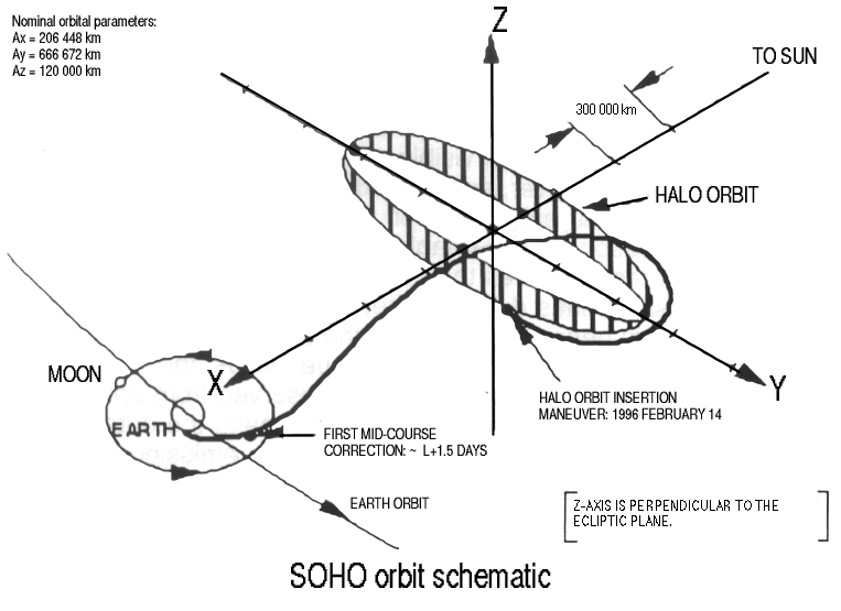