Sentinel-5P (or S-5P, or S5P) is an approved LEO pre-operational mission within the European GMES (Global Monitoring for Environment and Security) program — a collaborative effort of ESA and NSO (Netherlands Space Office). The goal is to fill the gap between the current atmospheric monitoring instruments SCIAMACHY on ESA's Envisat satellite and OMI (Ozone Monitoring Instrument) carried on NASA's Aura mission, as these instruments come to the end of their lifetimes, and the launch of the Sentinel-5 mission is planned for the timeframe 2020. Note: The Envisat mission operations ended on May 9, 2012. 1) 2) 3) 4)
|
Copernicus is the new name of the European Commission's Earth Observation Programme, previously known as GMES (Global Monitoring for Environment and Security). The new name was announced on December 11, 2012, by EC (European Commission) Vice-President Antonio Tajani during the Competitiveness Council. In the words of Antonio Tajani: “By changing the name from GMES to Copernicus, we are paying homage to a great European scientist and observer: Nicolaus Copernicus (1473-1543). As he was the catalyst in the 16th century to better understand our world, so the European Earth Observation Programme gives us a thorough understanding of our changing planet, enabling concrete actions to improve the quality of life of the citizens. Copernicus has now reached maturity as a programme and all its services will enter soon into the operational phase. Thanks to greater data availability user take-up will increase, thus contributing to that growth that we so dearly need today.” |
Table 1: Copernicus is the new name of the former GMES program 5)
The missions Sentinel-5P (LEO), Sentinel-4 (GEO) and Sentinel-5 (LEO) will be devoted to atmospheric composition monitoring for the GMES Atmosphere Service (GAS). The objective of the Sentinel-5P mission is to provide data delivery (maintain the continuity of science data) for atmospheric services between 2015-2020. The successor Sentinel-5 payload is planned to be flown on a MetOp-SG (Second Generation) mission with a launch in 2020.
At the ESA ministerial Conference in 2008 in The Hague, The Netherlands, the Sentinel-5P mission was defined in the frame of the ESA GMES Space Component Program. This program answers to a joint initiative of the EC (European Commission) and ESA on GMES.

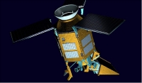
Figure 1: Sentinel-5P (SP5) is a gap-filler mission (image credit: Astrium) 6)
|
UV-VIS- NIR, SWIR |
TIR |
||||
|
Orbit |
LEO |
GEO |
LEO |
GEO |
|
|
Temporal sampling |
daily |
hourly |
daily |
hourly |
|
|
Instrument |
UVNS (UV NIR SWIR) Spectrometer |
TROPOMI |
UVN Spectrometer |
IAS (IR Atmospheric Sounder) |
IRS (IR Sounder) |
|
(Host) Satellite |
EPS-SG |
Free flyer |
MTG-S |
EPS-SG |
MTG-S |
|
Synergy |
VII (EPS Second Generation VIS/IR imager), |
VIIRS+OMPS+CRIS/NPP, /JPSS |
FCI/MTG-I (Flexible Combined Imager/Meteosat Third Generation-Imager) |
VII (EPS Second Generation VIS/IR imager) |
FCI /MTG-I (Flexible Combined Imager/Meteosat Third Generation-Imager) |
|
Sentinel-5P |
X |
||||
|
Sentinel-4 |
X |
X |
|||
|
Sentinel-5 |
X |
X |
|||
Table 2: Summary of the implementation scenarios of the Atmospheric Composition Sentinels 7)

Figure 2: Launch schedule of the Atmospheric Sentinels; the third Sentinel-5UVNS instrument is expected to be launched after 2030 (image credit: ESA)
Spacecraft:
Unlike the previous missions (Sentinel-1, Sentinel-2 and Sentinel-3), the Sentinel-4 and -5 will be in the class of “hosted payload” missions embarked on meteorological satellites and will be dedicated to atmospheric composition monitoring for the Copernicus Atmospheric Service. The mission is a single payload satellite embarking TROPOMI (Tropospheric Monitoring Instrument), a pushbroom instrument with four hyperspectral channels covering the spectrum from UV to SWIR. - On Dec. 8, 2011, ESA awarded a contract to Astrium Ltd. (Stevenage, UK) to act as prime contractor for the Sentinel-5 Precursor satellite system. 8) 9)
The satellite uses the AstroBus-L 250 M platform of Astrium and thus draws on the heritage from the SEOSat/Ingenio program of Spain, developed under the control of ESA, and from SPOT-6 and -7, two commercial imaging missions currently under development with Astrium internal funding. Including an ongoing export contract with Kazakhstan using this platform, Sentinel-5p is the 5th mission in the series and can rely on a robust and proven platform design. 10) 11)

Figure 3: Artist's view of the Sentinel-5P spacecraft in orbit (image credit: ESA, Airbus DS) 12)
The mechanical platform consists of a hexagonal structure supporting the platform electrical units and the TROPOMI ICU (Instrument Control Unit), and interfacing to a standard launch vehicle interface ring.
In the baseline solution, the platform equipment is distributed over the opening side panels, thus allowing easy access during integration and in case of on-ground maintenance operations.
The platform electrical/functional allocation uses a well proven classical architecture which is currently implemented in several ESA missions as well as in national and export programs. This proven architecture allows re-use of electronic equipment from several suppliers.
The core of the platform electrical/functional architecture is the data handling housed in two physically separate units, the OBC (On-Board Computer) and the RIU (Remote Interface Unit). The OBC (LEON 3) provides the processing and housekeeping memory functions and is responsible for telemetry and telecommand (TM/TC) handling, on-board time management, system re-configuration and communication with “intelligent” platform and payload units – units which communicate via a data bus. The OBC also manages the interface with the S-band transponder, which provides the RF telemetry, telecommand and ranging link to and from the ground station.
The OBC communicates with other satellite units primarily via two independent, fully redundant MIL-STD-1553B buses. All input/output interfaces to “non-intelligent” units are managed by the RIU.
The spacecraft power conditioning functions are performed autonomously by the PCDU (Power Conditioning and Distribution Unit). For robustness, these functions are implemented without the use of software. A battery and solar array sized to satisfy the mission needs complete the power subsystem.
The thermal subsystem includes heaters that are needed to maintain the thermal environment of the platform. The thermal control loops are controlled by the CSW (Central Software) resident in the OBC.
A COTS (Commercial-off-the Shelf) monopropellant propulsion module is used for orbit maintenance, mounted in the center of the lower floor. The propulsion subsystem is a hydrazine design operating in blow-down mode with 4 x 1 N thrusters configured in two redundant pairs.
The top floor accommodates the instrument and its radiator, as well as the star trackers and the X-band and S-band communication antennas. The instrument is mounted in a canted position, such that its radiator has an unobstructed field of view.
The nominal operational scenario for the payload instrument will always be nadir-pointing in the instrument imaging mode. Measurement data is collected when the SZA (Sun-Zenith Angle) is < 92º. Sun calibration can be performed close to the northern polar region when the sun enters the FOV (Field-of-View) of the sun calibration ports. Further calibration can be performed throughout the remainder of the orbit.
The PDHT (Payload Data Handling and Transmission) subsystem consists of a PDHU (Payload Data Handling Unit) and a set of X-band transmission units. The PDHU stores and handles the data transmitted by high speed links from the instrument. PUS (Packet Utilization Standard) compliant data are sent to the transponders and transmitted to ground.
The spacecraft is 3-axis stabilized, the design provides an optional yaw steering.

Figure 4: Fold-out illustration of the AstroBus-L elements (image credit: ESA)
The main features of the FDIR (Failure Detection, Isolation and Recovery) concept are:
• A robust and qualified design coming from a high level of reuse of the standardized operations and FDIR concept already implemented in SEOSat/Ingenio
• A hierarchical architecture (from unit level to system level) where the goal is to try to recover the observed error on the lowest possible level to maximize the system availability for nominal operations.
This FDIR design guarantees:
• A high level of autonomy for the nominal mission with extended periods of time without ground intervention
• Satellite integrity in case of any failure leading to suspend the nominal mission
• Maximizes the satellite availability and autonomy while preserving a robust and failure tolerant system
• Safe operation of the satellite in case of any credible anomaly
• Geo-location performance within requirements even after a single failure: the 3 Star Tracker Optical Heads ensure that the geo-location requirements are still met with some margin after the loss of one optical head.

Figure 5: Illustration of the Sentinel-5P spacecraft (image credit: ESA, Airbus DS)
EPS (Electrical Power Subsystem): Three deployable solar arrays (5.4 m2) using GaAs triple-junction solar cells, supply 1500 W of average power. The two Li-ion batteries have a capacity of 156 Ah.
RF communications: The spacecraft will be equipped with S-band and X-band communication channels for uplink commanding and housekeeping telemetry downlink and for the downlink of instrument data, respectively. The X-band payload downlink rate is 310 Mbit/s. The onboard mass memory unit has a capacity of 430 Gbit using flash memory technology.
Project development status:
• On October 13, 2017, Europe’s Sentinel-5P Earth observation mission will be lofted into space on a Russian rocket from Plesetsk Cosmodrome. About 93 minutes later, the satellite – having separated from the rocket and opened its solar panels – will transmit its first signals. The transmission will indicate that all has gone well with the launch and that the satellite is ready to receive instructions. 13)
- On Earth, engineers at the ground station in Kiruna, Sweden will be watching intently, with their 15 m diameter antenna pointing at the horizon, ready to catch Sentinel-5P’s signal as it rises into the sky over the country. - The Kiruna station is part of ESA’s global network, and it routinely supports multiple missions such as CryoSat, Integral, the Swarm trio and Sentinel.

Figure 6: Photo of the Kiruna station, located at Salmijärvi, 38 km east of Kiruna, in northern Sweden (image credit: ESA, CC BY-SA 3.0 IGO)
- At the same time, 2100 km to the south, the team at ESA’s mission control center in Darmstadt, Germany, will also be watching closely, because ‘acquisition of signal’ will mark the moment they assume control, sending commands and downlinking data to check on the satellite’s health and status.
• October 11, 2017: ESA’s air-quality mission Sentinel-5P will sift through light from the atmosphere to accomplish its ambitious monitoring goals. The Agency’s optics specialists helped to verify its main TROPOMI instrument would operate as planned. 14)
- Sentinel-5P is the first in a series of atmospheric chemistry missions from the European Commission’s Copernicus program. It carries a single high-precision optical payload called the TROPOMI (Tropospheric Monitoring Instrument), developed jointly by the Netherlands and ESA. - Its aim is to track gradual changes in the makeup of the atmosphere, providing continuity between past missions such as ESA’s Envisat and NASA’s Aura and Europe’s future Sentinel-4 and -5.

Figure 7: Test grating: Straylight performance verification measurements of a test grating for Sentinel-5P’s TROPOMI instrument, carried out in the ESTEC Optics Lab to ensure the delivery of quality measurements of Earth's atmosphere. These gratings are used to split light reflected from the atmosphere so that the spectral fingerprints of trace gases can be pinpointed (image credit: ESTEC Optics Laboratory/ESA)
- Orbiting at 824 km above our heads, Sentinel-5P will map a multitude of trace gases such as nitrogen dioxide, ozone, formaldehyde, sulphur dioxide, methane, carbon monoxide and aerosols – all of which affect the air we breathe and therefore our health, and our climate.
- The optimal performance of an optical instrument in space always comes down to the combination of its individual components – coatings, filters, lenses and mirrors – in the optical chain. So back during TROPOMI’s development phase, ESA’s Optics Laboratory tested a number of key instrument elements.

Figure 8: ESTEC optics laboratory angular resolved straylight measurement facility (image credit: ESA, S. Muirhead)
- TROPOMI works by comparing reflected light from Earth’s atmosphere with direct sunlight at various wavelengths, from infrared to ultraviolet. It uses diffraction gratings to split this light, allowing it to sift out the spectral fingerprints of its target trace gases.
- The optimal performance of an optical instrument in space always comes down to the combination of its individual components – coatings, filters, lenses and mirrors – in the optical chain. So back during TROPOMI’s development phase, ESA’s Optics Laboratory tested a number of key instrument elements.
- One of a suite of technical labs at ESA’s technical heart in the Netherlands, the Optics Lab focused on verifying controlling unwanted ‘stray light’ that might leak from the diffraction gratings. Too much stray light might make trace gas detection impossible. They performed precision measurements of prototype TROPOMI gratings to ensure any stray light remained within permissible bounds.

Figure 9: Sentinel-5P infographic: Mapping the global atmosphere every day, the Copernicus Sentinel-5P satellite provides high-resolution data on a multitude of trace gases and information on aerosols that affect air quality and climate (image credit: ESA, CC BY-SA 3.0 IGO)
• October 4, 2017: As preparations for the launch of Sentinel-5P continue on track, the team at Russia’s Plesetsk site has bid farewell to the satellite as it was sealed from view in the Rockot fairing. 15)
• Sept. 25, 2017: Engineers have been at Russia’s Plesetsk launch site for a month now, ticking off the jobs on the ‘to do’ list so that the Copernicus Sentinel-5P satellite is fit and ready for liftoff on 13 October. With the satellite now fuelled, the team has passed another milestone. 16)
• Sept. 4, 2017: The Sentinel-5P satellite has arrived in Plesetsk in northern Russia to be prepared for liftoff on 13 October. Built to deliver global maps of air pollutants every day and in more detail than ever before, this latest Copernicus mission will set a new standard for monitoring air quality. 17)
- Sentinel-5P is the first Copernicus mission dedicated to monitoring our atmosphere. It follows five other Sentinel satellites already in orbit and delivering a wealth of information about our planet.

Figure 10: Photo of the Sentinel-5P spacecraft arrival in Plesetsk (image credit: ESA)
• August 30, 2017: Today, Sentinel-5P was loaded on the Antonov aircraft that will take this latest Copernicus satellite to Russia to be prepared for liftoff in October. 18)
- Sentinel-5P carries the state-of-the-art TROPOMI instrument to map a multitude of trace gases such as nitrogen dioxide, ozone, formaldehyde, sulphur dioxide, methane, carbon monoxide and aerosols – all of which affect the air we breathe, our health, and our climate. With a swath width of 2600 km, it will map the entire planet every day. Information from this new mission will be used through the Copernicus Atmosphere Monitoring Service for air-quality forecasts and for decision-making.

Figure 11: Inside the cavernous Antonov (image credit: ESA)
• June 22, 2017: The Copernicus Sentinel-5 Precursor (Sentinel-5P) mission is dedicated to monitoring the composition of the atmosphere. Its data will be used largely by the Copernicus Atmosphere Monitoring Service. The mission will deliver information to monitor air quality, stratospheric ozone and will also be used for climate variables monitoring, and support European policy-making. 19)
- The Sentinel-5P mission will be the first of a series of atmospheric chemistry missions to be launched within the European Commission's Copernicus program. With the current launch window of September 2017 and a nominal lifetime of seven years, Sentinel-5P is expected to provide continuity in the availability of global atmospheric data products between its predecessor missions, SCIAMACHY (Envisat) and OMI (Aura), and the future Sentinel-4 and -5 missions.

Figure 12: Sentinel-5P Astrobus Platform Elements: The various elements that comprise the Sentinel-5P satellite, including the single payload instrument TROPOMI (image credit: ESA)
- Sentinel-5P products will be used by Copernicus Services, namely the Atmosphere Monitoring Service (CAMS) or the Climate Change Service (C3S). These services will transform its data into high value information (for instance, forecasts of air pollution over Europe) that can be used by decision-makers to take appropriate actions on environmental policies, from which the well-being and security of EC citizens and future generations depend.

Figure 13: European-scale air quality forecast of ozone: The CAMS (Copernicus Atmosphere Monitoring Service) provides European-scale air quality forecasts for every hour, up to 4 days in advance, supplied by the EURAD model. The maps provided are representative for large scale phenomena, and they cannot reproduce local aspects of air pollution (image credit: CAMS)
• Feb. 6, 2016: The launch service for ESA's Sentinel-5p satellite on the Rockot launch vehicle reached an important project milestone during this week. In the frame of the satellite’s test campaign at the facilities of Intespace, Toulouse, Sentinel-5P has been mated for the first time on its dedicated launch vehicle adapter. This adapter system will attach the spacecraft to the Rockot carrier during its travel into space and will eventually release the satellite into the target orbit. 20)
- The mating exercise, the so-called fit-check, aimed at verifying the mechanical and electrical interfaces between the Sentinel-5p satellite, built by Airbus DS in Stevenage, and the launcher hardware, manufactured by the rocketry company Khrunichev Research and Production Space Center. The purpose of a fit-check is ensuring a successful integration of the spacecraft onto Rockot at the launch complex and a check of the umbilical connections between the launcher and its payload. For the Sentinel-5P mission, the fit-check was further used to verify a customized purging system which was integrated into the adapter allowing the satellite customer to flush its contamination-sensitive instrument through the satellite-launcher interface during ground operations.

Figure 14: Sentinel-5P being lowered on the Rockot adapter ..... (image credit: Eurockot)
- The actual attachment of the Sentinel-5P satellite to its launch adapter is by means of a clamp band mechanism developed by Airbus Defence and Space in Madrid (formerly CASA Espacio). The clamp band is applied with high tension along the spacecraft-launch vehicle interface. The release of the satellite in space is achieved by firing pyro charges, which spontaneously open the clamp and hence allow separation. As the flawless functioning of the release is essential for a launch success, it was tested following the mating under recording the induced shock loads levels.
- Fit-check and release shock test have been conducted successfully on February 2nd and 3rd, respectively, in a remarkable team effort by Airbus Defence & Space, the Khrunichev Space Center, European Space Agency and Eurockot.

Figure 15: and mated with the Rockot launch vehicle adapter .... (image credit: Eurockot)

Figure 16: and separated again ..... (image credit: Eurockot)
• July 24, 2015: The Sentinel-5 Precursor platform and the TROPOMI instrument have been integrated together to form the satellite which will be leaving the UK for testing. Airbus DS will deliver the spacecraft to Intespace in Toulouse, France, for final system level testing. 21)
Launch: The Sentinel-5P spacecraft was launched on October 13, 2017 (09:27 GMT) on an Eurockot Rockot/Briz-KM vehicle from the Plesetsk Cosmodrome in northern Russia. The Sentinel-5P spacecraft has a launch mass of ~ 820 kg. The first stage separated 2 min 16 sec after liftoff, followed by the fairing and second stage at 3 min 3 sec and 5 min 19 sec, respectively. The upper stage then fired twice, delivering Sentinel-5P to its final orbit 79 min after liftoff. 22) 23) 24) 25)
Orbit: Sun-synchronous orbit, altitude = 824 km, inclination = 98.74º, LTAN (Local Time on Ascending Node) = 13.35 hours, period = 101 minutes, the repeat cycle is 17 days (227 orbits).
A unique feature of the Sentinel-5P mission lies in the synergistic exploitation of simultaneous measurements of imager data from the VIIRS (Visible/Infrared Imager and Radiometer Suite), embarked on the Suomi NPP (NPOESS Preparatory Project) satellite of NASA/NOAA. NASA launched the NPP mission on October 28, 2011. The Sentinel-5P orbit is selected such that it trails behind Suomi NPP by 5 min in LTAN, allowing the Sentinel-5P observation swath to remain within the scene observed by Suomi NPP.
Operational system/service allocations:
• The Sentinel-5P satellite consists of the platform and the TROPOMI payload, the latter is supplied as CFI (Customer Furnished Item) to the spacecraft prime.
• The LEOP (Launch and Early Orbit Phase) ground station network will be used to control spacecraft after launch.
• Svalbard polar Earth station for spacecraft operations and data downlinking.
• The FOS (Flight Operations Segment) function will be performed by ESA/ESOC.
• The PDGS (Payload Data Ground Segment) function will be performed by DLR/EOC (Earth Observation Center), under contract to Astrium Ltd. This involves the development of PDGS to host the missions' ground processors and to distribute the resulting data to the user community.
|
Spacecraft launch mass |
980 kg |
|
Spacecraft power |
1500 W (EOL), 430 W average power consumption, battery capacity = 156 Ah |
|
Spacecraft platform |
Astrobus L 250 M (Astrium UK) |
|
Onboard storage capacity |
480 Gbit (redundant) mass memory capacity) |
|
Science data link |
310 Mbit/s, modulation: OQPSK (Offset Quadrature Phase Shift Keying) |
|
Mission lifetime |
7 years with reliability of 0.75 |
|
TROPOMI instrument mass |
206.6 kg, plus 17.4 kg for the instrument control unit |
|
TROPOMI swath width |
2600 km (kept within the 3000 km VIIRS swath of Suomi NPP) |
|
Observation pointing |
Fixed nadir pointing – accuracy requirements are easily met by typical EO satellites |
|
Observation periods |
Observation + calibration typically 89% of orbit |
|
Data collected / orbit |
139 Gbit |
|
Data downlink |
Once per orbit. No data loss if the downlink is missed for one orbit |
|
Spacecraft autonomy |
Command loading for 7 days |
|
Payload thermal control |
Passive, use of a 1.5 m2 radiator |
Table 3: Overview of some mission parameters

Figure 17: Sentinel-5P team set-up (image credit: Astrium)
Note: As of June 2019, the previously large Sentinel5P file has been split into two files, to make the file handling manageable for all parties concerned, in particular for the user community.
• This article covers the Sentinel-5P mission plus the mission status in the period 2020
• Sentinel-5P Status and Imagery for the period 2019
• Sentinel-5P Mission Status for the period 2018-2017
Mission status and imagery for the period 2020 + 2021
• March 4, 2021: For the first time, scientists, using satellite data from the Copernicus Sentinel missions, are now able to detect individual methane plumes leaking from natural gas pipelines around the globe. 26)
- Methane is one of the most potent greenhouse gases, second only to carbon dioxide in its overall contribution to climate change. The energy sector, including oil, natural gas and coal, is one of the largest sources of methane emissions. According to the International Energy Agency (IEA), oil and gas operations worldwide emitted just over 70 Mt of methane into the atmosphere in 2020 alone.
- Until recently, the debate surrounding methane emissions during natural gas transportation has been focused on defective installations and devices resulting in small, ‘fugitive’ or unintended emissions. Thanks to powerful technologies, such as high-resolution satellite data, scientists are now able to underline the impact of frequent and intentional methane releases, also known as ‘venting.’
- In 2020, Kayrros, a European technology start-up, successfully developed a tool to accurately detect individual methane emissions from space. Now, the platform is being used to track regular methane emissions along gas pipelines, for example in Siberia, with emission rates of up to 300 tons per hour recorded.
- By combining data from the Copernicus Sentinel-5P and Sentinel-2 missions, along with artificial intelligence algorithms, Kayrros scientists detected 13 methane emission events, with rates up to 164 tonnes per hour in 2019-2020, along the Yamal-Europe pipeline – a 4196 km pipeline running across Russia, Belarus, Poland and Germany.

Figure 18: Emission hotspots detected around natural gas pipelines including the Yamal-Europe and ‘Brotherhood’ pipelines (image credit: ESA, the image contains modified Copernicus data (2020), processed by Kayrros)
- Another 33 emission events, with rates up to 291 tons per hour, were detected over the same period on the shorter, Brotherhood pipeline. When contacted, operators confirmed that these events were related to planned maintenance and have been duly reported to the relevant authorities.
- Remarkably, the number of emission events detected by Kayrros increased by 40% over Russia in 2020 from 2019, even though the COVID-19 pandemic helped cut Russian gas exports to Europe by an estimated 14%, according to the IEA.
- Over the same period, Kayrros also detected major methane releases in the US, from numerous emissions associated with shale oil production, as well as in other countries such as Kazakhstan.

Figure 19: The images show methane hotspots over a gas pipeline in Kazakhstan detected by the Copernicus Sentinel-5P mission (left) and Copernicus Sentinel-2 mission (right), image credit: ESA, the images contain modified Copernicus data (2020), processed by Kayrros
- Many methane emissions take place during transportation, as operators choose to vent the gas during routine maintenance operations, which sometimes results in a ‘double-cloud’ pattern on Sentinel-5P images. These events, however, could easily and cost-effectively be avoided by using alternative operational practices such as portable flaring.
- Antoine Rostand, President of Kayrros, said, “The climate footprint of these operational practices is enormous because of the global warming potential of methane – 84 times greater than carbon dioxide over 20 years. The venting observed by Kayrros along Russian pipelines in 2019 and 2020 released methane equivalent to approximately 3 Mt of carbon dioxide, which could have been avoided.”
- “We now have the technology to align with our ambitions. It’s time to use it.”
- ESA’s Copernicus Sentinel-5P Mission Manager, Claus Zehner, commented, “Kayrros’ use of Copernicus Sentinel-2 and Sentinel-5P images to detect methane hotspots is not only a major technical achievement but is hugely beneficial for the planet. It shows how cutting-edge innovation can leverage data from the Copernicus programs to deliver benefits beyond what could have been imagined when these programs were initially launched.”

Figure 20: The image on the left shows examples of large methane concentrations in non-oil and gas producing regions in the US, potentially due to pipeline maintenance. The image on the right shows a map of pipelines in the same region [image credit: ESA, the image contains modified Copernicus data (2020), processed by Kayrros (left); U.S. Energy Information Administration (right)]

Figure 21: Many methane emissions take place during transportation, as operators choose to vent the gas during routine maintenance operations, which sometimes results in a ‘double-cloud’ pattern on Sentinel-5P images, such as this image of Russia in July 2020. These events, however, could easily and cost-effectively be avoided by using alternative operational practices such as portable flaring (image credit: ESA, the image contains modified Copernicus data (2020), processed by Kayrros)
• December 14, 2020: Scientists have used satellite data from the Copernicus Sentinel-2 mission, combined with the Sentinel-5P satellite, to detect individual methane emissions from space. 27)
- While carbon dioxide is more abundant in the atmosphere, and therefore more commonly associated with global warming, methane is more potent as a heat-trapping gas. It usually enters the atmosphere mainly from landfill sites, livestock farming, rice agriculture and the fossil fuel industry – particularly during coal, oil and gas extraction and transportation.
- Until recently, no straightforward solution has existed to detect individual methane emissions and track them back to their original sources. The Copernicus Sentinel-5P satellite, launched in 2017, is the first Copernicus mission dedicated to monitoring the atmosphere and is the first satellite to provide regular imagery of Earth for emission detection. However, the spatial resolution of its measurements limited the ability to correctly attribute methane emissions to their sources.
- Now, scientists from Kayrros, a European technology start-up, have succeeded in developing a tool that can accurately detect individual methane emissions. By combining data from the Sentinel-5P satellite with measurements from the Copernicus Sentinel-2 infrared spectral range channels, scientists can now easily detect, quantify and attribute methane emissions to their sources.
- This was first demonstrated during the summer of 2020, when a methane leak occurred in the Permian Basin – a major shale oil and gas production region in the United States. The leak was detected and quantified on 24 September 2020 by an aerial campaign commissioned by the Environmental Defense Fund, a leading international non-profit organization.
- Despite being detected, it was impossible to identify when the leak had started or the volume of methane released. The combination of Sentinel-2 and Sentinel-5P satellite data, with Kayrros technology, was used to identify the leak.

Figure 22: Methane hotspot detected with Copernicus Sentinel-2 imagery. The image shows the methane hotspot detected with Copernicus Sentinel-2 imagery. The image of the location is displayed on the left, while the corresponding methane enhancement image can be seen on the right. This clearly shows the methane plumes over the area (image credit: ESA, the image contains modified Copernicus data (2020), processed by Kayrros)
- Antoine Rostand, President of Kayrros, said, “The results showed that the leak began on 4 July 2020, and that it had been detected 12 times between that date and its final disappearance on 26 September. Using proprietary quantification algorithms, we ascertained that these 12 quantifications ranged between five and 20 tonnes of methane per hour.”
- Kayrros had previously detected other methane plumes over the same location during the summer, but this was the first clear spotting of the event using both Copernicus Sentinel-2 and Copernicus Sentinel-5P data in a synergistic way.
- “Using Copernicus Sentinel-2 images for methane hotspot detection is a major technical breakthrough as the satellite was not initially designed for this particular purpose,” commented Claus Zehner, ESA’s Copernicus Sentinel-5P Mission Manager. “This is important for methane monitoring efforts as the use of these data allows for the constant monitoring of oil and gas production areas around the world and will support the implementation of the recently released European Commission Methane strategy.”

Figure 23: The image shows the methane cloud as detected by Copernicus Sentinel-5P on 24 September 2020 (image credit: ESA, the image contains modified Copernicus data (2020), processed by Kayrros)
• November 9, 2020: For the first time, scientists, using data from the Copernicus Sentinel-5P satellite, are now able to detect nitrogen dioxide plumes from individual ships from space. 28)

Figure 24: Nitrogen dioxide emissions over the Mediterranean. For the first time, scientists, using data from the Copernicus Sentinel-5P satellite, are now able to detect nitrogen dioxide plumes from individual ships from space. This image shows the nitrogen dioxide emission patterns in dark red over the central Mediterranean Sea on 2 July 2018 (image credit: ESA, the image contains modified Copernicus Sentinel data (2018), processed by Georgoulias et al.)
- Maritime transport has a direct impact on air quality in many coastal cities. Commercial ships and vessels burn fuel for energy and emit several types of air pollution as a by-product, causing the degradation of air quality. A past study estimated that shipping emissions are globally responsible for around 400,000 premature deaths from lung cancer and cardiovascular disease, and 14 million childhood asthma cases each year.
- For this reason, during the past decade, efforts to develop international shipping emission regulations have been underway. Since January 2020, the maximum sulphur dioxide content of ship fuels was globally reduced to 0.5% (down from 3.5%) in an effort to reduce air pollution and to protect health and the environment. It is expected that the nitrogen dioxide emissions from shipping will also become restricted during the coming years.
- Monitoring ships to comply with these regulations is still an unresolved issue. The open ocean covers vast areas, with limited or no capacity to perform local checks. This is where satellites, such as the Copernicus Sentinel-5P satellite, come in handy.
- Until recently, satellite measurements needed to be aggregated and averaged over months or even years to discover shipping lanes, limiting the use of satellite data for regulation control and enforcement. Only the combined effect of all ships could be seen, and only along the busiest shipping lanes.
- In a recent paper, an international team of scientists from the Royal Netherlands Meteorological Institute (KNMI), Wageningen University, the Human Environment and Transport Inspectorate of the Ministry of Infrastructure and Water Management, the Aristotle University of Thessaloniki and the Nanjing University of Information Science & Technology, have now discovered patterns in previously unused ‘sun glint’ satellite data over the ocean that strongly resemble ship emission plumes.

Figure 25: Nitrogen dioxide concentration patterns under sun glint conditions. For the first time, scientists, using data from the Copernicus Sentinel-5P satellite, are now able to detect nitrogen dioxide plumes from individual ships from space. The image shows the nitrogen dioxide patterns under sun glint viewing conditions, as well as 10-meter wind fields from the ECMWF operational model analyses, and AIS ship locations from the last three hours before, and up to, Sentinel-5P's overpass time. Dark magenta colors are used for the ship positions close to the satellite's overpass time and brighter magenta colors for earlier ship positions. -Image B is an example of the original AIS locations (dots) and the wind-shifted plume locations (crosses) of a ship (Ship 6) at the time of TROPOMI's overpass. - Image C is the same as Image A but for the projected wind-shifted plume locations of the 40 ships with a length larger than 200 m. The ships are numbered according to their nitrogen dioxide levels. Dark magenta colors are used for ship plumes emitted close to the satellite's overpass time and brighter magenta colors for earlier ship plumes (image credit: ESA, the image contains modified Copernicus Sentinel data (2018), processed by Georgoulias et al.)
- Sun glint occurs when sunlight reflects off the surface of the ocean at the same angle that a satellite sensor views it. As water surfaces are irregular and uneven, the sunlight is scattered in different directions, leaving blurry streaks of light in the data.
- Satellite algorithms tend to mistake such bright surfaces for cloudiness, which is why, for a long time, sun glint was considered a nuisance in satellite measurements. Differentiating clouds from other bright reflective surfaces such as snow, clouds or even sun glint over the ocean surface has proven difficult – until now.
- In a study published last year, scientists were able to differentiate snow and ice from clouds by measuring the height of the cloud and comparing it with the surface elevation. If the height of the cloud is found to be sufficiently close to the surface, it can be considered either snow or ice, rather than cloud coverage.
- When applying the same method for sun glint over oceans, the team were able to easily identify and attribute emissions from individual ships in daily Sentinel-5P measurements.
- Aris Georgoulias, from the University of Thessaloniki, commented, “By combining these measurements with ship location information, and taking into account the effect of wind blowing emission plumes away from ship smoke stacks, we could show that these structures almost perfectly matched the ship tracks.”
- “For now, only the largest ships, or multiple ships travelling in convoy, are visible in the satellite measurements,” added Jos de Laat, from KNMI. “Ship tracks from small ships never aligned with these emission plume structures, unless their tracks crossed the track of larger ships or large shipping lanes, or a small ship travelled in a busy shipping lane.”
- Claus Zehner, ESA’s Sentinel-5P Mission Manager, commented, “We think that these new results demonstrate exciting possibilities for the monitoring of ship emissions in support of environmental regulation from space. Future planned satellite missions with improved spatial resolution, for example the Copernicus Anthropogenic Carbon Dioxide Monitoring satellites, should allow for the better characterization of nitrogen dioxide ship emission plumes and, possibly, detection of smaller ship plumes.”

Figure 26: Sun glint pattern as seen in satellite data from the VIIRS instrument on the Naomi NPP satellite of NASA/NOAA on 2 July 2018. The dark spots in the middle of the sun glint are locations where the sea surface is nearly flat (lack of wind waves) and acts as a true mirror, in which case the sun glint effect disappears(image credit: NASA)
• October 19, 2020: Measurements from the Copernicus Sentinel-5P satellite show that this year’s ozone hole over the Antarctic is one of the largest and deepest in recent years. A detailed analysis from the German Aerospace Center indicates that the hole has now reached its maximum size. 29)
- The size of the ozone hole fluctuates on a regular basis. From August to October, the ozone hole increases in size – reaching a maximum between mid-September and mid-October. When temperatures high up in the stratosphere start to rise in the southern hemisphere, the ozone depletion slows, the polar vortex weakens and finally breaks down, and by the end of December ozone levels return to normal.
Figure 27: The animation shows the size of the ozone hole from 25 September 2020 until 18 October 2020. Measurements from the Copernicus Sentinel-5P satellite show that this year’s ozone hole over the Antarctic is one of the largest in recent years. A detailed analysis from the German Aerospace Center indicates that the hole has now reached its maximum size (video credit: the video contains modified Copernicus Sentinel data (2020), processed by DLR/BIRA/ESA)
- This year, measurements from the Copernicus Sentinel-5P satellite, show that this year’s ozone hole reached its maximum size of around 25 million km2 on 2 October, comparable to the sizes of 2018 and 2015 (where the area was around 22.9 and 25.6 million km2 in the same period). Last year, the ozone hole not only closed earlier than usual, but was also the smallest hole recorded in the last 30 years.
- The variability of the size of the ozone hole is largely determined by the strength of a strong wind band that flows around the Antarctic area. This strong wind band is a direct consequence of Earth's rotation and the strong temperature differences between polar and moderate latitudes.
- If the band of wind is strong, it acts like a barrier: air masses between polar and temperate latitudes can no longer be exchanged. The air masses then remain isolated over the polar latitudes and cool down during the winter.
- Diego Loyola, from the German Aerospace Center, comments, “Our observations show that the 2020 ozone hole has grown rapidly since mid-August, and covers most of the Antarctic continent – with its size well above average. What is also interesting to see is that the 2020 ozone hole is also one of the deepest and shows record-low ozone values. The total ozone column measurements from the TROPOMI instrument on Sentinel-5P reached close to 100 Dobson Units on 2 October.”

Figure 28: Depth of the 2020 ozone hole. The 2020 ozone hole is also one of the deepest. Measurements from the Copernicus Sentinel-5P satellite show that this year’s ozone hole has reached its maximum depth with a peak of around 100 DU on 2 October (image credit: the image contains modified Copernicus Sentinel data (2020), processed by DLR/BIRA/ESA)
- ESA’s mission manager for Copernicus Sentinel-5P, Claus Zehner, adds, “The Sentinel-5P total ozone columns provide an accurate means to monitor ozone hole occurrences from space. Ozone hole phenomena cannot be used in straightforward manner for monitoring global ozone changes as they are determined by the strength of regional strong wind fields that flow around polar areas.”
- In the 1970s and 1980s, the widespread use of damaging chlorofluorocarbons in products such as refrigerators and aerosol tins damaged ozone high up in our atmosphere – which led to a hole in the ozone layer above Antarctica.
- In response to this, the Montreal Protocol was created in 1987 to protect the ozone layer by phasing out the production and consumption of these harmful substances, which is leading to a recovery of the ozone layer.
- Claus concludes, “Based on the Montreal Protocol and the decrease of anthropogenic ozone-depleting substances, scientists currently predict that the global ozone layer will reach its normal state again by around 2050.”
- ESA has been involved in monitoring ozone for many years. Launched in October 2017, Copernicus Sentinel-5P satellite is the first Copernicus satellite dedicated to monitoring our atmosphere. With its state-of-the-art instrument, TROPOMI, it is able to detect atmospheric gases to image air pollutants more accurately and at a higher spatial resolution than ever before from space.

Figure 29: Size of the 2020 ozone hole. The measurements from the TROPOMI instrument on the Copernicus Sentinel-5P satellite show that this year's ozone hole has reached its maximum size with a peak of around 25 million km2 (black dots on the right-hand plot). The ozone hole covers most of the Antarctic continent and the size is well above the average of the last ten years (grey area on the right figure), image credit: the image contains modified Copernicus Sentinel data (2020), processed by DLR/BIRA/ESA)
• September 18, 2020: Air pollution is one of the biggest environmental problems of our time. According to a new report from the European Environment Agency (EEA), air pollution now accounts for one in eight deaths in Europe. Observations from the Copernicus Sentinel-5P satellite have been vital in tracking the evolution of air pollution, specifically nitrogen dioxide concentrations, across Europe. 30)
- This year, satellite data have been widely used to monitor fluctuations in air quality brought on by strict COVID-19 measures. The Copernicus Sentinel-5P satellite, part of the European Copernicus program, has been continuously mapping changes of air pollution since its launch in 2017.
- Scientists from the Royal Netherlands Meteorological Institute (KNMI) and the Royal Belgian Institute for Space Aeronomy (BIRA-IASB) have used satellite data from Sentinel-5P and ground-based data in order to pinpoint the correlation between COVID-19 and the effects of air pollution across Europe.

Figure 30: These images, using data from the Copernicus Sentinel-5P satellite, show the average nitrogen dioxide concentrations from March to April (upper panels) and July to August (lower panels) in 2019 and 2020, and their difference maps. After a strong column decrease observed during the lockdown in March-April 2020, the majority of Europe returned to similar 2019 levels of nitrogen dioxide concentrations, except for large cities, where the nitrogen dioxide levels remain lower than in 2019 (image credit: ESA, the imagery contains modified Copernicus Sentinel data (2019-20), processed by KNMI/BIRA-IASB)

Figure 31: This graph shows the averaged nitrogen dioxide (NO2) concentrations over five major European cities. The upper panel shows concentrations (using a 14-day moving average) in 2019 compared to 2020 using data from the Copernicus Sentinel-5P satellite, while the lower panel shows in situ observations. - The shades of grey denote the lockdown periods in 2020, moving progressively from strict (dark grey) to loose (light grey) measures. The percentages shown in red represent the column reduction in 2020 compared to 2019 over the same period (image credit: ESA, the images contain modified Copernicus Sentinel data (2019-20), processed by KNMI/BIRA-IASB)
- The data shows that the strongest reductions of 40–50% were seen in the first stage of the lockdown in southern Europe, specifically Spain, Italy and France. In July and August 2020, the data suggests that the concentrations are still 10% to 20% lower than pre-COVID levels.
- Bas Mijling, atmospheric scientist at KNMI, comments, “Quarantine measures implemented in Berlin led to a drop of about 20% with small variations seen until August 2020. In eastern Europe, the impact of the measures has been generally less dramatic than in southern Europe, and in France, where reductions of approximately 40–50% were observed during the strict lockdowns of March and April.
- “More research is currently taking place as part of ESA’s ICOVAC project, or impact study of COVID-19 lockdown measures on air quality and climate.”
- Jenny Stavrakou, atmospheric scientist at BIRA-IASB, adds, “The impact of meteorology on the nitrogen dioxide observations could be significant and should not be overlooked. This is why it is necessary to analyze data over longer periods of time, to better estimate the impact of human activity on the observations.”
- She continues, “For the monthly mean comparison of 2019 and 2020, we estimate an uncertainty on the COVID-19 induced reduction of around 15–20%. By comparing the reductions in satellite based data and ground-based data for different cities, we find a satisfactory agreement differences lying well within the uncertainties due to meteorological variability.”
- ESA’s Copernicus Sentinel-5P Mission Manager, Claus Zehner, says, “What is really remarkable is the good agreement between the Sentinel-5P satellite data and the ground-based measurements. This demonstrates that air quality monitoring from space can contribute to regular air quality reporting in European countries, which has been only done, so far, using ground-based measurements.”

Figure 32: This graph shows the averaged nitrogen dioxide concentrations over the Ruhr region, Scheldt estuary, Po Valley and South England. The graphs shows concentrations (using a 14-day moving average) in 2019 compared to 2020 using data from the Copernicus Sentinel-5P satellite. - The shades of grey denote the lockdown periods in 2020, moving progressively from strict (dark grey) to loose (light grey) measures. The percentages shown in red represent the column reduction in 2020 compared to 2019 over the same period (image credit: ESA, the images contain modified Copernicus Sentinel data (2019-20), processed by KNMI/BIRA-IASB)
- The lockdowns around March–April in Europe led to significant drops of nitrogen dioxide levels across densely populated and industrialized areas of Europe, including the Ruhr region in Germany and the Po Valley in northern Italy.
- These decreases are attributed to the significant contribution of traffic, as well as of the industrial and energy sectors to nitrogen dioxide levels. The concentrations appear to return to near-normal levels in July–August 2020, except over large cities where human activities have not yet fully resumed.
- Nitrogen dioxide is released into the atmosphere during fuel combustion from vehicles, power plants, and industrial facilities and can have significant impacts on human health – increasing the likelihood of developing respiratory problems. The Copernicus Sentinel-5P carries the TROPOMI instrument – a state-of-the-art instrument that detects the unique fingerprint of atmospheric gases to image air pollutants more accurately and at a higher spatial resolution than ever before.
• September 17, 2020: Copernicus Sentinel-5P’s high revisit rate combined with GHGSat’s high-resolution commercial imagery can give landfill operators and regulators the information they need to reduce methane emissions from landfill sites. 31)
- As a potent greenhouse gas, methane is becoming an increasing concern. Later this year, the EU will issue a Methane Strategy, which includes uncontrolled emissions from landfill sites as a priority target for reducing methane emissions within the European Green Deal.
- Accurate measurements of concentrations of methane are key to identifying particular sources and to adopting strategies to mitigate emissions. Until now, however, satellite systems measuring methane have been of insufficient resolution to attribute emissions from individual landfill sites.
- Working with Benito Roggio Ambiental (BRA), the waste management operator responsible for one of the largest landfill sites in South America, and the Netherlands Institute for Space Research (SRON), scientists have been analyzing Sentinel-5P data to guide GHGSat’s demonstration high-resolution satellite, Claire, to measure methane emissions from individual waste management facilities.

Figure 33: Captured by GHGSat’s Claire mission on 15 February 2020, this image shows concentrations of methane from the Norte III landfill site in Buenos Aires, Argentina. GHGSat is a New Space initiative that draws on Copernicus Sentinel-5P data for mapping methane hotspots [image credit: GHGSat (background ©2020 Google map data)]
- GHGSat’s new Iris satellite, which was taken into orbit on 2 September 2020 on ESA’s Vega rocket, provides even higher spatial resolution and improved detection to collect methane measurements for smaller sources.
- Copernicus Sentinel-5P’s high revisit rate combined with GHGSat’s high-resolution imagery is enabling new analytics solutions that can support landfill operators and regulators reduce the cost of inspection, regularly screen for emissions and identify opportunities to recover landfill gas, for example.
- Scientists from SRON and GHGSat are developing synergetic approaches for monitoring methane emission sources including waste management facilities in the EU and globally.

Figure 34: One year averaged methane concentrations over Buenos Aires observed by the TROPOMI instrument on Copernicus Sentinel-5P. The black square denotes the location for GHGSat to target. TROPOMI data are analyzed by SR ON Netherlands Institute for Space Research to guide GHGSat and other high-resolution instruments towards large methane emitters (image credit: ESA, the image contains Copernicus Sentinel data (2019–1920), processed by SRON)
- The Sentinel-5P data analyzed by SRON can be used to point high-resolution instruments such as GHSat’s demonstration satellite Claire and its new Iris satellite towards large methane sources. With these advances in high-resolution data and new analytics approaches, ESA anticipates significant progress on this practical application in the coming months and years.
- Rodrigo Pontiggia, BRA Development and Innovation Manager says, “BRA has various initiatives to safely collect and use land-fill gas from the Norte III site. The size of the landfill presents unique challenges and we are impressed with the early results that GHGSat has delivered to characterize our methane emissions.
- “We look forward to exploring the enhanced capabilities presented by Iris and the ways in which we can incorporate GHGSat data into our operations on a recurring basis.”
- GHGSat’s Director of Business Development (Europe), Adina Gillespie, comments, “Together with BRA, we will initiate a new project to collectively evaluate Iris data for achievable commercial as well as operational integration into management of the Norte III landfill site. This project will build on the current ESA study being undertaken by the UK National Physical Laboratory and GHGSat.”
- The ESA study is using methane measurements of a UK landfill site to evaluate satellite and ground measurement capability for its applicability to monitoring oil & gas pipelines. The results from this study will help guide the BRA follow-on developments.
- In anticipation of the data from Iris, ESA, the Canadian Space Agency and GHGSat have teamed up through an announcement of opportunity to make 5% of the data available for research purposes, including waste management studies.
• July 29, 2020: Methane may not be as abundant in the atmosphere as carbon dioxide, but with a global warming potential many times greater than carbon dioxide, monitoring and controlling industrial emissions of this potent gas is imperative to helping combat climate change. GHGSat is a New Space initiative that draws on Copernicus Sentinel-5P data for mapping methane hotspots – and its Claire satellite has now collected more than 60 000 methane measurements of industrial facilities around the world. 32)
- Copernicus Sentinel-5P’s role is to map a range of atmospheric gases around the globe every 24 hours. Its TROPOMI spectrometer delivers data with a resolution as high as 7 km x 5.5 km for methane, but these data can’t be used to pinpoint specific facilities responsible for emissions.
- However, GHGSat’s demonstration satellite ‘Claire’ can, but it is helped with a bit of guidance from Sentinel-5P.
- Drawing on Sentinel-5P data, the GHGSat tasks Claire to home in on methane point sources. Using this approach, GHGSat has been able to attribute large methane leaks to specific industrial facilities. This is catching the attention of managers responsible for emissions from industries such as oil and gas, waste management, mining, agriculture and power generation.
- The Climate Investments arm of the Oil & Gas Climate Initiative (OGCI) has taken particular interest, including an investment in GHGSat.
- Managing Director of Ventures for OGCI Climate Investments, Rhea Hamilton, says, “GHGSat’s methane monitoring product has achieved impressive results and is attractive to oil and gas operators.
- “The company has identified significant methane leaks and supported operators in understanding the results, prompting corrective action. OGCI Climate Investments looks forward to watching GHGSat grow to serve more operators.”
- Following on from the Claire demonstrator, GHGSat plans to have a constellation of 10 satellites operating by 2022. The next satellite, Iris, which will be able to spot even smaller methane leaks, is one of the 53 satellites that will be launched on the Vega VV16 flight, scheduled for mid-August.
- ESA’s Director of Earth Observation Programs, Josef Aschbacher, commented, “Copernicus Sentinel-5P and Claire working together is a prime example of institutional satellites working hand in hand with commercial satellites, a concept that is taking Earth observation into a new era.
- “We are very much looking forward to seeing Iris launch as a next step towards better greenhouse gas monitoring.”
- Iris will offer a spatial resolution of 25 m compared to Claire’s 50 m resolution, therefore allowing methane to be traced even more accurately.

Figure 35: GHGSat’s commercial satellite 'Iris' during testing (mass of 16 kg). Iris is scheduled to launch in August 2020 and will measure sources of the potent greenhouse gas, methane, at higher resolution than has previously been possible. Industrial site operators will use Iris measurements alongside Copernicus Sentinel-5P and Claire measurements to better understand their greenhouse gas emissions, enabling them to control and, ultimately, reduce them(image credit: GHGSat)
- Alongside augmented satellite performance coming from Iris, GHGSat is addressing a growing demand for analytics services and predictive models. For example, dedicated methane analytics and reporting is possible for asset managers and stakeholders responsible for environmental, social and governance (ESG) factors for understanding investment risk and growth opportunity.

Figure 36: Methane plume from oil & gas infrastructure in the Caspian Sea region. Captured by GHGSat’s Claire mission on 21 May 2020, this image shows methane emissions from an onshore oil & gas facility in the Caspian Sea Region. GHGSat is a New Space initiative that draws on Copernicus Sentinel-5P data for mapping methane hotspots. Its Claire satellite has now collected more than 60 000 methane measurements of industrial facilities around the world [image credit: GHGSat (background © 2020 Google map data)]
- GHGSat President and CEO, Stephane Germain, makes analytics a priority to answer specific market needs. He comments, “GHGSat’s analytics are of growing interest for industrial operators in all sectors, as they are accelerating their efforts to mitigate emissions. With this in mind, GHGSat is building on its expertise in Canada and has advanced plans for an international analytics center delivering for ESG in the financial sector.”

Figure 37: Working together to monitor greenhouse gases. With the climate crisis high on the global political agenda and the issue of greenhouse gases a serious concern, today also saw ESA, the Canadian Space Agency and the Canadian GHGSat company sign a Memorandum of Intent. The new collaboration will entail the provision of free data from the GHGSat constellation to the scientific community and support global efforts to monitor greenhouse gases and improve our understanding of chemical and physical atmospheric processes. Back row from left to right: Giuseppe Ottavianelli, ESA's Earth Observation PROBA-1 and Third Party Mission Manager, Simonetta Cheli, Head of Strategy, Program & Coordination Office for ESA's Earth Observation Programs, Johann-Dietrich Wörner, ESA Director General and Adina Gillespie, Director of Business Development, Europe at GHGSat Inc. Front row: Josef Aschbacher, ESA's Director of Earth Observation Programs and Stéphane Germain, President and Chief Executive Officer at GHGSat Inc.)
- In anticipation of the data from Iris, ESA, the Canadian Space Agency and GHGSat have teamed up through an announcement of opportunity to make 5% of Iris data freely available for research purposes.
• July 9, 2020: Every summer, the wind carries large amounts of desert dust particles from the hot and dry Sahara Desert in northern Africa across the Atlantic Ocean. Data from the Copernicus Sentinel satellites and ESA’s Aeolus satellite show the extent of this year’s summer dust plume, dubbed ‘Godzilla,’ on its journey across the Atlantic. 33)
- This Saharan dust storm is also known as the Saharan Air Layer, which typically forms between late spring and early autumn, peaking in late June to mid-August. Large amounts of dust particles from the African desert are swept up into the dry air by strong winds near the ground, as well as thunder storms. The dust can then float for days, or weeks, depending on how dry, fast and turbulent the air masses become. Winds in the higher troposphere then sweep the dust across the Atlantic Ocean towards the Caribbean and the United States.
- Although this meteorological phenomenon occurs every year, the June 2020 plume is said to be unusual owing to its size and the distance travelled. According to NOAA’s Atlantic Oceanographic and Meteorological Laboratory, the dust plume was around 60—70% dustier than an average outbreak – making it the dustiest event since records began around 20 years ago.
Figure 38: The Copernicus Sentinel-5P mission is dedicated to monitoring air pollution by measuring a multitude of trace gases as well as aerosols. This animation shows the spread of aerosols from the Saharan dust plume moving westward across the Atlantic Ocean from 1 June to 26 June 2020. This plume has reached the Caribbean, South America and the United States (video credit: ESA, this video contains modified Copernicus Sentinel data (2020), processed by ESA, CC BY-SA 3.0 IGO)

Figure 39: This composite image shows combined observations from the Aeolus satellite and the Copernicus Sentinel-5P satellite on 19 June 2020. The underlying Sentinel-5P aerosol index in florescent yellow and green, which indicates the extent of the elevated Saharan dust plume over the Atlantic, has been overlaid with information from Aeolus’ aerosol and cloud data. In yellow, parts of the laser light are scattered and absorbed by the Saharan dust (image credit: ESA, the image contains Copernicus and Aeolus data (2020), visualized with VirES)
Note: VirES for Aeolus is a highly interactive data manipulation and retrieval interface for ESA's Aeolus mission products. It includes tools for studying various atmospheric parameters, in space and time, measured by the Aeolus satellite.
- Aeolus data provides valuable information regarding the altitude and vertical extent of the aerosol layer, compared to downward-looking imagers, as it can determine the height at which the dust layer is travelling. Aeolus data in this image indicates that most of the dust was 3—6 km above the ground.
- These data are extremely important for air quality models used by, for example, the Copernicus Atmosphere Monitoring Service, to predict how far the dust layer will travel and how it develops, and therefore, the effects it will have locally.
- Different satellites carry individual instruments that provide us with a wealth of complementary information. While the Copernicus Sentinel-5P satellite maps a multitude of air pollutants around the globe, Aeolus is the first satellite mission to acquire profiles of Earth’s wind on a global scale. As shown here, Aeolus also delivers information about the vertical distribution of aerosol and cloud layers. This combination of satellite data allow scientists to improve their understanding of the Saharan Air Layer, and allows forecasters to provide better air quality predictions.

Figure 40: In this image, captured by the Copernicus Sentinel-2 mission, dust particles can be seen over Sao Filipe on 20 June 2020 (image credit: ESA, the image contains modified Copernicus Sentinel data (2020), processed by ESA, CC BY-SA 3.0 IGO)
- While the dust poses a threat for our health, causing hazy skies and triggering air quality alerts, the travelling Saharan dust plays an important role in our ecosystem. The dust is a major source of nutrients which are essential for phytoplankton – microscopic marine plants that drift on or near the surface of the ocean. Some of the minerals from the dust falls into the ocean, triggering blooms of phytoplankton to form on the ocean surface, which in turn provides food on which other marine life depends.
- The dust is also essential for life in the Amazon. It replenishes nutrients in rainforest soils – nutrients that would otherwise be depleted by frequent rainfall in this tropical region.
- The dry and dusty air layers have also been shown to suppress the development of hurricanes and storms in the Atlantic. Tropical storms need warm ocean waters and warm humid air in order to form. If a storm were to develop, it would collide with the dusty and dry layers of air of the Saharan dust cloud, preventing it from growing further.
• July 1, 2020: Concentrations of sulphur dioxide in polluted areas in India have decreased by around 40% between April 2019 and April 2020. Using data from the Copernicus Sentinel-5P satellite, from the European Union Copernicus program, scientists have produced new maps which show the drop in concentrations across the country in times of COVID-19. 34)
- In a report by Greenpeace last year, India was named the world’s largest emitter of anthropogenic sulphur dioxide – a significant contributor to air pollution. Sulphur dioxide causes many health-related problems, can harm sensitive ecosystems and is also a precursor to acid rain.
- While some atmospheric sulphur dioxide is produced from natural processes, such as volcanoes, a substantial amount is produced by human activities – predominantly from power plants burning fossil fuels.
- In India, emissions of sulphur dioxide have strongly increased over the last ten years, exacerbating haze problems over large parts of the country. However, owing to the COVID-19 pandemic, human and industrial activity dropped considerably since the beginning of its lockdown on 25 March 2020.
- Sulphur dioxide concentrations have dropped significantly compared to the previous year, notably over New Delhi, over many large coal-fired power plants as well as other industrial areas. Some large plants in the northeast states of Odisha, Jharkhand, and Chhattisgarh have maintained a substantial level of activity, while others appear to have ceased entirely.

Figure 41: Based on measurements gathered by the Copernicus Sentinel-5P satellite, the map shows the averaged concentrations of sulphur dioxide over India from April 2019, compared to April 2020. The darker shades of red and purple depict greater concentrations of sulphur dioxide in the atmosphere. Sulphur dioxide mainly comes from industrial processes and causes many health-related problems (image credit: ESA, the image contains modified Copernicus data (2019-20), processed by BIRA-IASB)
- This analysis was produced by using data from the TROPOMI instrument on the Copernicus Sentinel-5P satellite. A recent algorithm improvement, completed by the Royal Belgian Institute for Space Aeronomy (BIRA-IASB), allows the team to better picture the evolution of anthropogenic sulphur dioxide emissions over the country.
- Nicolas Theys, from BIRA-IASB, comments, “We are very pleased with the new algorithm development as it is very sensitive to low sulphur dioxide concentrations caused by anthropogenic activities. As compared to the operational processor, the sensitivity and accuracy for anthropogenic emission detection has increased by an order of magnitude.”
- ESA’s Copernicus Sentinel-5P mission manager, Claus Zehner, adds, “With our operational product, we can reliably measure strong sulphur dioxide concentrations emitted by volcanoes, but we have problems in detecting anthropogenic sulphur dioxide emissions. This new algorithm will enable new applications, for example in verifying existing sulphur dioxide emission inventories, after it has been implemented into the operational Sentinel-5P processing chain at the German Aerospace Center.”
• June 11, 2020: A new online platform that allows for the tracking of air pollution worldwide is now available to the public. The maps, which use data from the Copernicus Sentinel-5P satellite, show the averaged nitrogen dioxide concentrations using a 14-day moving average. The maps not only show changes over time on a global scale, but also provide the possibility for users to zoom in to areas of interest, for example any city or region over Europe. 35)
- Nitrogen dioxide concentrations in our atmosphere vary widely on a day-to-day basis owing to the fluctuations of emissions, as well as variations in weather conditions such as sunlight, temperature and wind, all of which can affect the lifetime of the gas in the atmosphere.
- For these reasons, it is necessary to analyze data over a substantial period of time – in this case 14 days – as it allows for the accurate mapping and analysis of nitrogen dioxide concentrations across the globe.
- Nitrogen dioxide is produced from power plants, vehicles and other industrial facilities and can have significant impacts on human health – increasing the likelihood of developing respiratory problems.
- With air quality a serious concern, the Copernicus Sentinel-5P satellite was launched in 2017 to map a multitude of air pollutants around the globe. Copernicus Sentinel-5P carries the TROPOMI instrument – a state-of-the-art instrument that detects the unique fingerprint of atmospheric gases to image air pollutants more accurately and at a higher spatial resolution than ever before.
- The mapping service is part of the Sentinel-5P Product Algorithm Laboratory (S5P-PAL) – an ongoing project funded by the European Commission. S5P-PAL is a project that allows fast and cost-efficient Sentinel-5P prototype product development (for example bromine monoxide and water vapor) and the generation of higher level products like global maps. New mapping services for the carbon monoxide product and additional functionalities, for example the selection of an area and time-period to investigate time-series of measurements, are currently in development.
- The mapping service is available here: https://maps.s5p-pal.com/
- The S5P-PAL is also part of the new ‘Rapid Action on Coronavirus and Earth observation’ dashboard, also known as RACE. The platform provides access to key environmental, economic and social indicators to measure the impact of the coronavirus lockdown and monitor post-lockdown recovery.

Figure 42: The averaged maps also reflect the effects of the COVID-19 lockdown – with drastic reductions of nitrogen dioxide concentrations visible over many areas. These effects can now be easily explored across the globe (image credit: ESA, the image contains modified Copernicus Sentinel data (2020), processed by S[&]T)
• June 1, 2020: While carbon dioxide is more abundant in the atmosphere and therefore more commonly associated with global warming, methane is around 30 times more potent as a heat-trapping gas. Given its importance, Canadian company GHGSat have worked in collaboration with the Sentinel-5P team at SRON Netherlands Institute for Space Research to investigate hotspots of methane emissions during COVID-19. 36)
- Carbon dioxide is generally produced by the combustion of fossil fuels, while fossil fuel production is one of the largest sources of methane emissions. According to the World Meteorological Organization's State of the Global Climate report last year, current carbon dioxide and methane concentrations represent respectively 150% and 250% of pre-industrial levels, before 1750.
- Owing to the importance of monitoring methane, SRON’s and GHGSat’s research teams have been working since early-2019 to detect methane hotspots. The SRON team uses data from the Copernicus Sentinel-5P satellite to detect emissions on a global scale. The GHGSat team then utilizes data from GHGSat satellites to quantify and attribute the emissions to specific facilities around the world.
- Their work has led to several new hotspots being discovered in 2020, for instance over a coal mine in China. The team have also detected methane emissions over the Permian Basin – the largest oil-producing region in the United States. The team observed concentrations from March-April 2020, compared to the same period as last year in an effort to evaluate the impact of COVID-19 activities on methane emissions.

Figure 43: Methane concentrations over the Permian Basin. GHGSat uses data from the Copernicus Sentinel-5P satellite to detect emission hotspots in various regions – including the Permian Basin. The image on the left shows the enhanced methane concentrations over the Permian basin, while the image on the right highlights the exact facility in the Permian Basin leaking methane (image credit: GHGSat)
- An initial look at these data suggest a substantial increase in methane concentrations in 2020, compared to 2019. Claus Zehner, ESA’s Copernicus Sentinel-5P mission manager, says, “An explanation for this could be that as a result of less demand for gas because of COVID-19, it is burned and vented – leading to higher methane emissions over this area.”
- Ilse Aben, from SRON, comments, “However, these results are inconclusive when using only Sentinel-5P data in the Permian Basin as the number of observations are limited.”
- The spatial distribution of Sentinel-5P concentrations in 2020 and in 2019 both indicate local enhancements of methane concentrations in the Delaware and Midland portions of the basin. But higher-resolution measurements, such as those provided by GHGSat, are needed to attribute these enhancements to specific facilities.
- The joint analysis of GHGSat and Sentinel-5P regional methane data will continue to explore and quantify how COVID-19 is affecting emissions from the natural gas industry on a regional scale – all the way down to the level of industrial facilities.

Figure 44: TROPOMI methane measurements over a coal mine in the Shanxi province, China. GHGSat have worked in close collaboration with the Sentinel-5P team at SRON Netherlands Institute for Space Research to investigate hotspots of methane emissions. The team uses data from the Copernicus Sentinel-5P satellite to detect emissions on a global scale, and then utilizes data from GHGSat satellites to quantify and attribute emission to specific facilities around the world. -This has led to several new hotspots being discovered including a coal mine in the Shanxi province, China (image credit: ESA, the image contains modified Copernicus Sentinel data (2018, 2020), processed by SRON)
- Stephane Germain, CEO of GHGSat, comments, “GHGSat continues to work closely with ESA and SRON’s Sentinel-5P science team. We are advancing the science of satellite measurements of atmospheric trace gases while simultaneously providing practical information to industrial operators to reduce facility-level emissions. GHGSat’s next satellites, scheduled to launch in June and December of this year, will help improve our collective understanding of industrial emissions around the world."
- Eric Laliberté, Director General Utilization from the Canadian Space Agency, says, “The Canadian Space Agency is committed to developing space technologies and supporting innovative missions to better understand and mitigate climate change. The results achieved by GHGSat are already having an impact and we are excited to continue working with GHGSat and ESA to better understand greenhouse gas emissions worldwide."
- Claus adds, “In order to further support the scientific uptake of GHGSat measurements, ESA has organized, together with the Canadian Space Agency and GHGSat, a dedicated Announcement of Opportunity Call that will provide around 5% of the measurement capacity of the upcoming commercial GHGSat-C1, also known as the Iris satellite, to the scientific community.”
- The Copernicus Sentinel-5P satellite, with its state-of-the-art instrument TROPOMI, can also map other pollutants such as nitrogen dioxide, carbon monoxide, sulphur dioxide and aerosols – all of which affect the air we breathe.

Figure 45: GHGSat methane concentrations over a coal mine in the Shanxi province, China. This image shows GHGSat methane concentrations over a coal mine in the Shanxi province, China (image credit: GHGSat)
• May 15, 2020: As the COVID-19 pandemic has disrupted lives across the globe, Earth-observing satellites take the pulse of our planet from space. While the global lockdown has had a massive impact on daily life and the economy, there have been environmental benefits that are visible from space. How can we preserve these positives when returning to ‘business as usual’? 37)
Figure 46: Seen from space: COVID-19 and the environment. This video includes an interview in English with Josef Aschbacher, Director of Earth Observation Programs (video credit: ESA)
• May 05, 2020: Half of humanity is being affected by the lockdown measures implemented as a result of the Coronavirus pandemic. The strong global decrease of nitrogen dioxide (NO2) concentrations, when compared to the levels detected over the previous year by the European Sentinel-5P satellite is therefore not surprising. Nitrogen oxides are an indicator of air pollution from industrial and transport activities. 38)
- However, the comparison is deceptive. This year, polar winds over large parts of Europe and a persistent westerly wind, which prevented the accumulation of pollutants, already provided unusually clean air. Assessing the impact of the Coronavirus on this is therefore complex. Researchers from the German Aerospace Center (Deutsches Zentrum für Luft- und Raumfahrt; DLR) Earth Observation Center (EOC) have obtained scientifically sound evidence of the 'Corona' effect.

Figure 47: Comparison of nitrogen dioxide emissions over Europe between March/April 2019 and 2020 [image credit: DLR (CC-BY 3.0)]

Figure 48: Comparison of nitrogen dioxide emissions over Asia between 2019 and 2020 [image credit: DLR (CC-BY 3.0)]

Figure 49: Comparison of nitrogen dioxide emissions in North America between March/April 2019 and 2020 [image credit: DLR (CC-BY 3.0)]
- The situation in North America between mid-March and April is similar to that in Europe on a year-on-year basis. Here, the reduction of tropospheric nitrogen dioxide on the east coast and especially in the region around New York is of the order of 30 percent. The weather-related fluctuations were reduced by creating monthly averages. These averages were calculated over the period from 16 March to 15 April. No adjustments for the influence of the weather on the combination of long-term satellite observations, in-situ measurements and model calculations were made – as described in the text.
• May 04, 2020: An important new tool to combat climate change is now available. Using data from the Copernicus Sentinel-5P satellite, this new technology makes it possible to track and attribute methane emissions around the world. 39)

Figure 50: This image shows a sample of abnormal methane concentrations over 2019. The size and color of the circles indicate the size and intensity of the plume detected. The redder the color, the higher the concentration of the methane plume (image credit: ESA, the image contains modified Copernicus Sentinel data (2019), processed by Kayrros)
- Methane is the second most important greenhouse gas and its concentration in the atmosphere is currently increasing at a rate of around 1% per year. It effectively absorbs heat from the sun, more so than carbon dioxide, and contributes significantly to the warming of the atmosphere. As a result, there is a growing demand to track and regulate methane emissions.
- Scientists from Kayrros, a European technology start-up, have recently developed a platform to monitor methane emissions on a global scale. Their findings come from a technology that leverages Copernicus Sentinel-5P data along with additional information from a range of other sources – such as ground sensor data, position tracking and social media data.
- In addition to these, supplementary data from the Copernicus Sentinel-1 and Sentinel-2 missions was also used, resulting in the ability to pinpoint the location, potency and size of methane leaks around the world.

Figure 51: In December 2019, Kayrros detected a methane plume over the Permian Basin in the US using data from the Copernicus Sentinel-5P satellite. The Permian Basin is a shale play – an oil and gas region with a high density of wells – meaning there were hundreds of potential sources of the leak. Kayrros therefore used data from the Copernicus Sentinel-2 and Sentinel-1 missions to look into which wells had completed operations within three months of the leak – a factor that would significantly narrow down the potential suspects. The result was that only one operator was in this category. - The example of the Permian Basin shows how the use of the Copernicus Sentinel satellites, in combination with Kayrros’s technology, can be used to narrow down the source of a methane leak. Whilst Sentinel-5P allowed the initial detection, it was only through the use of Sentinel-2 and Sentinel-1 that the final source could be identified (image credit: Kayrros)
- The Kayrros studies show that there are around 100 high volume-emitting methane leaks at any one time around the world. Around 50% of these emissions come from regions with activities in oil and gas, coal mining and other heavy industries.
- Jean Bastin, Product Manager at Kayrros, explains, “Over one year, those 100 leaks are releasing 20 megatons of methane, with around half of those attributable to the oil and gas sector and other heavy industries. This means that this sector emits an amount of methane that is equivalent to the yearly carbon dioxide emissions of both Germany and France combined.”
- The International Energy Agency’s recent Methane Tracker underlined the importance of satellite data for precise detection data. Prior to this technology, engineering estimates remained the basis of most benchmarks on methane levels. This new ability to provide real-time detection of methane will profoundly change the direction of climate policy, and the benefits of the new technology are multiple.
- ESA’s Director of Earth Observation Programs, Josef Aschbacher, says “In the public sector, the use of observed data on methane emissions instead of untested assumptions on methane intensity, will improve the accuracy of annual inventories of greenhouse emissions. For governments and regulators, this technology will enable better decisions on energy policy if they can establish a baseline for methane emissions and monitor changes in carbon intensity as they happen.”
• April 25, 2020: Findings published in the journal Science Advances show that oil and gas operations in America's sprawling Permian Basin are releasing methane at twice the average rate found in previous studies of 11 other major U.S. oil and gas regions. The new study was authored by scientists from Environmental Defense Fund (EDF), Harvard University, Georgia Tech and the SRON Netherlands Institute for Space Research. 40) 41)

Figure 52: The Permian Basin is the largest oil field on the planet. Tens of thousands of wells dot the 86,000 square mile landscape that spans West Texas and Southeastern New Mexico [image credit: EDF (Environmental Defense Fund), Nick Simonite]
- "These are the highest emissions ever measured from a major U.S. oil and gas basin. There's so much methane escaping from Permian oil and gas operations that it nearly triples the 20-year climate impact of burning the gas they're producing," said co-author Dr. Steven Hamburg, chief scientist at EDF. "These findings demonstrate the rapidly growing ability of satellite technology to track emissions like these and to provide the data needed by both companies and regulators to know where emissions reductions are needed."
- Based on 11 months of satellite data encompassing 200,000 individual readings taken across the 160,000 km2 basin by the European Space Agency's TROPOMI instrument from May 2018 to March 2019, Permian oil and gas operations are losing methane at a rate equal to 3.7% of their gas production. The wasted methane - which is the main component in natural gas - is enough to supply 2 million U.S. households.
- Methane (CH4) is a potent greenhouse gas, human emissions of which cause over a quarter of today's warming. Reducing methane from oil and gas operations is the fastest, most cost-effective way to slow the rate of warming, even as the necessary transition to a net-zero carbon economy continues.
Findings highlight crucial new applications
- Satellites offer an important new methane measurement tool that can cover large areas faster and more frequently than conventional methods. They can also provide data on gas producing regions around the world that are impossible to reach by aircraft or from the ground.
- "Advances in satellite technology and data analytics are making it possible to generate regular and robust information on methane emissions from oil and gas operations even from the most remote corners of the world," said Mark Brownstein, EDF senior vice president for Energy. "It's our goal to use this new data to help companies and countries find, measure, and reduce methane emissions further and faster, and enable the public to both track and compare progress."
- Launched in 2017, the TROPOMI instrument on the Sentinel-5P satellite used in the study offers more precise measurements, higher resolution and better coverage than its forerunners. It is part of an emerging ecosystem of methane-tracking satellites with a growing range of capabilities, including one with even higher precision currently being developed by EDF subsidiary MethaneSAT LLC for launch in 2022. MethaneSAT will track oil and gas methane around the globe on a near-weekly basis, identifying and measuring smaller emission events and more widely dispersed sources not discernable with current technology.
Permian emissions challenge
- The Permian Basin has emerged as one of the world's most prolific oil-producing regions in recent years, producing 3.5 million barrels of crude and 11 billion cubic feet of natural gas per day (about 30% and 10% of the respective U.S. totals in 2018).
- Today's new peer-reviewed findings validate a set of ground-based and airborne measurements released two weeks ago by EDF's PermianMAP initiative, which found methane escaping from oil and gas operations in the most productive part of the basin at a rate of 3.5%. That project is currently collecting a year's worth of methane data across a 10,000 km2 study area within the basin via fixed-wing aircraft, helicopters, towers, and ground-based mobile sensors.
- High leakage rates in the Permian imply the opportunity to greatly reduce methane emissions in this sprawling oil and gas producing region, through better infrastructure design and development, more effective operations and better regulation at both the state and federal levels.
- The TROPOMI study uses the latest technology and methods available to analyze and present data, a process that currently takes a great deal of time and effort. But researchers are quickly learning how to automate and accelerate these complex calculations. The MethaneSAT project, for example, is expected to deliver data based on weekly measurements in near-real time.
- "Early TROPOMI images showed that the Permian was one of the largest methane hotspots in the U.S. But the satellite was new, and data analysis hadn't even started. Quantifying emissions and deriving a leak rate for a huge area was a big, hands-on effort, even with the best tools," said EDF's Dr. Ritesh Gautam, one of the study's lead researchers. "Studies like this are expanding those boundaries. MethaneSAT and missions that follow will be more capable, delivering more data much faster, in ways that are more actionable by stakeholders."
• April 24, 2020: Lockdowns imposed to halt the spread of the coronavirus have been recently linked with cleaner air quality over Europe and China. New images, from the Copernicus Sentinel-5P satellite, from the European Union Copernicus program, now show some cities across India seeing levels drop by around 40–50% owing to its nationwide quarantine. 42)
- On 25 March 2020, the Indian government placed its population of more than 1.3 billion citizens under lockdown in an effort to reduce the spread of the COVID-19 disease. All non-essential shops, markets and places of worship were closed with only essential services including water, electricity and health services remaining active.
- New satellite maps, produced using data from the Copernicus Sentinel-5P satellite, show averaged nitrogen dioxide concentrations over India from 1 January to 24 March 2020 and 25 March (the first day of the lockdown) to 20 April 2020 – compared to the same time-frame as last year.

Figure 53: These images, using data from the Copernicus Sentinel-5P satellite, show the average nitrogen dioxide concentrations from 1 January to 24 March 2020 and 25 March (the first day of the lockdown) to 20 April 2020 – compared to the same time-frame as last year. The significant reduction in the concentrations can be seen over major cities across India. Mumbai and Delhi saw drops of around 40-50% compared to the same time last year. A trail of nitrogen dioxide emissions from maritime traffic can be seen as a faint line over the Indian Ocean (visible in the bottom of the image.) Shipping lanes appear as straight lines owing to commercial ships following more or less the same route. The concentrations of nitrogen dioxide in our atmosphere vary widely on a daily basis. Variations owing to weather conditions make it necessary to average data over substantial periods of time – allowing for more accurate assessments to be made (image credit: ESA, the image contains modified Copernicus Sentinel data (2019-20), processed by ESA, CC BY-SA 3.0 IGO)
- Claus Zehner, ESA’s Copernicus Sentinel-5P mission manager, says, “Thanks to the TROPOMI instrument on the Copernicus Sentinel-5P satellite, we are able to observe such high reductions in concentrations in Europe, China, and now India because of the national quarantine measures put in place.
- “What is interesting in these new maps are the high values of nitrogen dioxide concentrations over northeast India. Our analysis shows that these clusters are directly linked with the locations of the ongoing coal-based power plants. The largest power station in India, the Vindhyachal Super Thermal Power Station, shows a reduction of only around 15% compared to the same time last year.”
- According to a recent report by Reuters, India’s electricity consumption fell by 9.2% in March 2020. Using data from the Power System Operation Corp Ltd (POSOCO), they found that consumers used 100.2 billion kilowatt hours (kWh) in March 2020, compared with 110.33 billion units from 2019.
- ESA’s Director of Earth Observation Programs, Josef Aschbacher, comments, “Another interesting feature we can see from these images is the maritime traffic across the Indian Ocean. We can clearly see a faint trail of nitrogen dioxide emissions left in the atmosphere as commercial ship traffic appears almost the same as last year. The shipping lanes appear as a straight line because the ships follow more or less the exact same route.”
- Nitrogen dioxide is usually emitted into the atmosphere as a result from power plants, industrial facilities and vehicles – increasing the likelihood of developing respiratory problems. Because concentrations in our atmosphere vary widely on a daily basis, it is necessary to analyze data over substantial periods of time – allowing for more accurate assessments to be made.
- Claus comments, “Weather variability is an important factor to consider when making assessments such as these, which is why our team has averaged the data over a longer period of time. In this case, we can clearly see the decreased concentrations are due to human activity.”
- Air pollution is a major environmental health problem that affects people in developed and developing countries alike. According to the World Health Organization (WHO), air pollution kills an estimated seven million people worldwide each year.
- According to a report using data from the World Air Quality Report from IQAir, Indian cities make up six of the world’s ten most-polluted urban areas. Air pollution in New Delhi, considered the world’s most polluted city, is caused by fumes from sclerotic traffic, the burning of fossil fuels, as well as industrial activity.
- Josef Aschbacher, says, “It has never been more important to monitor the air we breathe. As we have seen over the previous months, the Copernicus Sentinel-5P satellite is the best satellite equipped to monitor nitrogen dioxide concentrations on a global scale”
- With more than 23,000 reported cases of coronavirus across the country, India’s Prime Minister Narendra Modi has extended the nationwide lockdown until at least 3 May.

Figure 54: These images, using data from the Copernicus Sentinel-5P satellite, show the average nitrogen dioxide (NO2) concentrations from 25 March to 20 April 2019 and average concentrations from 25 March to 20 April 2020. The spikes in the top image show concentrations from 2019 over Delhi and Mumbai. Owing to COVID-19 restrictions, the 2020 image shows high concentrations in northeast India, which coincides with the ongoing activity in coal-based power plants in east India (image credit: ESA, the image contains modified Copernicus Sentinel data (2019-20), processed by ESA, CC BY-SA 3.0 IGO)
• April 16, 2020: Further analyses are showing the continued low levels of nitrogen dioxide (NO2) concentrations across Europe – coinciding with lockdown measures implemented to stop the spread of the coronavirus. New data from the Copernicus Sentinel-5P satellite, from the European Union Copernicus program, show some cities seeing levels fall by 45—50% compared to the same period last year. 43)
- Scientists from the Royal Netherlands Meteorological Institute (KNMI) have been monitoring air pollution over Europe in the past months using data from the TROPOMI instrument of the Copernicus Sentinel-5P satellite.
- Nitrogen dioxide is produced from power plants, vehicles and other industrial facilities and can have significant impacts on human health – increasing the likelihood of developing respiratory problems. Nitrogen dioxide concentrations in our atmosphere vary widely day to day owing to the fluctuations of emissions, as well as variations in weather conditions.
- This weather-induced variability proves difficult to draw conclusions based only on daily or weekly measurements, making it necessary to analyze data over a substantial period of time to iron out any anomalies.
- Henk Eskes, from the Royal Netherlands Meteorological Institute (KNMI), comments, “There are considerable variations of weather in every country from one day to the next, creating a large impact on the dispersion of nitrogen dioxide.
- “Averaging data over longer periods of time allows us to see clearer changes in concentrations owing to human activity. For this reason, the maps show concentrations over a monthly period and are provided with an uncertainty of 15% which reflects weather variability not accounted for in the monthly averages used.”
- As lockdown measures will continue in the following weeks, the KNMI team will continue to work on a more detailed analysis of other countries in northern Europe, where a larger variability in data owing to changing weather conditions is observed.
- Making use of air-quality models, such as the Copernicus Atmosphere Monitoring Service, as well as combining results from in situ data, will narrow down the impact of changes in weather on air pollution estimates.

Figure 55: The new images show the nitrogen dioxide concentrations from 13 March until 13 April 2020, compared to the March-April averaged concentrations from 2019. Madrid, Milan and Rome saw decreases of around 45%, while Paris saw a dramatic drop of 54% – coinciding with the strict quarantine measures implemented across Europe (image credit: ESA, the images contain modified Copernicus Sentinel data (2019-20), processed by KNMI/ESA)
• April 06, 2020: Scientists using data from the Copernicus Sentinel-5P satellite have noticed a strong reduction of ozone concentrations over the Arctic. Unusual atmospheric conditions, including freezing temperatures in the stratosphere, have led ozone levels to plummet – causing a ‘mini-hole’ in the ozone layer. 44)
- The ozone layer is a natural, protective layer of gas in the stratosphere that shields life from the Sun’s harmful ultraviolet radiation – which is associated with skin cancer and cataracts, as well as other environmental issues.
- The ‘ozone hole’ most commonly referenced is the hole over Antarctica, forming each year during autumn.
- In the past weeks, scientists from the German Aerospace Center (DLR) have noticed the unusually strong depletion of ozone over the northern polar regions. Using data from the TROPOMI instrument on the Copernicus Sentinel-5P satellite, they were able to monitor this Arctic ozone hole form in the atmosphere.
Figure 56: Scientists from the German Aerospace Center (DLR), using data from the Copernicus Sentinel-5P satellite, have noticed an unusual ozone hole form over the Arctic. This animation shows the daily ozone levels over the Arctic from 9 March 2020 until 1 April 2020 (video credit: this animation includes modified Copernicus data (2020), processed by DLR/BIRA/ESA)
- In the past, mini ozone holes have occasionally been spotted over the North Pole, but the depletion over the Arctic this year is much larger compared to previous years.
- Diego Loyola, from the German Aerospace Center, comments, “The ozone hole we observe over the Arctic this year has a maximum extension of less than 1 million km2. This is small compared to the Antarctic hole, which can reach a size of around 20 to 25 million km2 with a normal duration of around 3 to 4 months.”
- Even though both poles endure ozone losses during winter, the Arctic’s ozone depletion tends to be significantly less than Antarctica. The ozone hole is driven by extremely cold temperatures (below -80ºC), sunlight, wind fields and substances such as chlorofluorocarbons (CFCs).
- Arctic temperatures do not usually plummet as low as in Antarctica. However, this year, powerful winds flowing around the North Pole trapped cold air within what is known as the ‘polar vortex’ – a circling whirlpool of stratospheric winds.
- By the end of the polar winter, the first sunlight over the North Pole initiated this unusually strong ozone depletion – causing the hole to form. However, its size is still small compared to what can usually be observed in the southern hemisphere.
- Diego says, “Since 14 March, the ozone columns over the Arctic have decreased to what is normally considered ‘ozone hole levels,’ which are less than 220 Dobson Units. We expect the hole to close again during mid-April 2020.”
- Claus Zehner, ESA’s Copernicus Sentinel-5P mission manager, adds, “The TROPOMI total ozone measurements are extending Europe’s capability of the continuous global ozone monitoring from space since 1995. In this time, we have not witnessed an ozone hole formation of this size over the Arctic.”
- In the 2018 Scientific Assessment of Ozone Depletion, data shows that the ozone layer in parts of the stratosphere has recovered at a rate of 1-3% per decade since 2000. At these projected rates, the Northern Hemisphere and mid-latitude ozone is predicted to recover by around 2030, followed by the Southern Hemisphere around 2050, and polar regions by 2060.
- The TROPOMI instrument on the Copernicus Sentinel-5P satellite measures a number of trace gases, including aerosol and cloud properties with a global coverage on a daily basis. Given the importance of monitoring air quality and global ozone distribution, the upcoming Copernicus Sentinel-4 and Sentinel-5 missions will monitor key air quality trace gases, stratospheric ozone, and aerosols. As part of the EU’s Copernicus program, the missions will provide information on air quality, solar radiation and climate monitoring.

Figure 57: Air quality monitoring for Copernicus. Sentinel-5P is the first Copernicus mission dedicated to monitoring our atmosphere. This new satellite carries the state-of-the-art TROPOMI instrument to map a multitude of trace gases and aerosols that affect the air we breathe and our climate. Sentinel-5P is the forerunner of the Sentinel-5 instrument that will be carried on the MetOp Second Generation weather satellites, the first of which is expected to be operational around 2021. Until then, Sentinel-5P will play an essential role in providing data for forecasting and monitoring air quality around the world (image credit: ESA/ATG medialab)
• March 27, 2020: New data, based on observations from the Copernicus Sentinel-5P satellite, are showing strong reductions in nitrogen dioxide concentrations over several major cities across Europe – including Paris, Madrid and Rome. 45)
- The coronavirus disease (COVID-19) has been spreading rapidly across the world – affecting 170 countries with more than 530,000 confirmed cases worldwide. The coronavirus outbreak was declared a global pandemic by the World Health Organization, and has since stated that the disease is ‘accelerating’.

Figure 58: Nitrogen dioxide concentrations over France. These images, using data from the Copernicus Sentinel-5P satellite, show the average nitrogen dioxide concentrations from 14 to 25 March 2020 (right), compared to the monthly average concentrations from 2019 (left), image credit: ESA, the images contain modified Copernicus Sentinel data (2019-20), processed by KNMI/ESA, CC BY-SA 3.0 IGO
- In order to curb the spread of the COVID-19 outbreak, countries across the world are implementing strict measures – placing cities and even entire countries on lockdown.
- The Copernicus Sentinel-5P satellite has recently mapped air pollution across Europe and China and has revealed a significant drop in nitrogen dioxide concentrations – coinciding with the strict quarantine measures.
- Scientists from the Royal Netherlands Meteorological Institute (KNMI) have been using data from Copernicus Sentinel-5P satellite to monitor both weather and pollution over Europe.
- The new images clearly illustrate a strong reduction of nitrogen dioxide concentrations over major cities across Europe – specifically Milan, Paris and Madrid.

Figure 59: Nitrogen dioxide concentrations over Spain. This image, using data from the Copernicus Sentinel-5P satellite, shows the average nitrogen dioxide concentrations from 14 to 25 March 2020, compared to the monthly average concentrations from 2019 (image credit: ESA, the image contains modified Copernicus Sentinel data (2019-20), processed by KNMI/ESA)
- Henk Eskes, from KNMI, explains why these dates were chosen, “The nitrogen dioxide concentrations vary from day to day due to changes in the weather. Conclusions cannot be drawn based on just one day of data alone.
- He continues, “By combining data for a specific period of time, 10 days in this case, the meteorological variability partly averages out and we begin to see the impact of changes due to human activity.”
- “The chemistry in our atmosphere is non-linear. Therefore, the percentage drop in concentrations may differ somewhat from the drop in emissions. Atmospheric chemistry models, which account for daily changes in weather, in combination with inverse modelling techniques are needed to quantify the emission based on the satellite observations.”
- The KNMI team, in collaboration with scientists worldwide, have started to work on a more detailed analysis using ground data, weather data and inverse modelling to interpret the concentrations observed, in order to estimate the influence of the shutdown measures.
- Henk comments, “For quantitative estimates of the changes in the emissions due to transportation and industry, we need to combine the TROPOMI data from the Copernicus Sentinel-5P satellite with models of atmospheric chemistry. These studies have started, but will take some time to complete.”
- Other countries in northern Europe are being closely monitored, including the Netherlands and the United Kingdom – but scientists have observed a larger variability owing to changing weather conditions. New measurements from this week will help to assess the changes in nitrogen dioxide over northwest Europe.
- Claus Zehner, ESA’s Copernicus Sentinel-5P mission manager, says, “The special features of the Copernicus Sentinel-5P satellite, with its high spatial resolution and accurate ability to observe trace gases compared to other atmospheric satellite missions, allows for the generation of these unique nitrogen dioxide concentration measurements from space.”
- ESA’s Director of Earth Observation Programs, Josef Aschbacher, says, “The long-term cooperation between ESA and KNMI proves very valuable and shows the importance of complementary analyses by different partner organizations. As we can see, the Copernicus Sentinel-5P satellite is the best satellite equipped to monitor nitrogen dioxide concentrations on a global scale.”

Figure 60: Nitrogen dioxide concentrations over Italy. These images, using data from the Copernicus Sentinel-5P satellite, show the average nitrogen dioxide concentrations from 14 to 25 March 2020, compared to the monthly average concentrations from 2019 (image credit: ESA, the images contain modified Copernicus Sentinel data (2019-20), processed by KNMI/ESA, CC BY-SA 3.0 IGO)
• March 19, 2020: Recent data have shown a decline of air pollution over northern Italy coinciding with its nationwide lockdown to prevent the spread of the coronavirus disease (COVID-19). This new map shows the variation of nitrogen dioxide emissions over China from December to March – thanks to the TROPOMI instrument on board the Copernicus Sentinel-5P satellite. 46)
- As news of the coronavirus broke out in the Hubei province, China, in late December 2019, stricter measures were put in place. As a result, by late January, factories were closed and streets were cleared as Chinese authorities had ceased daily activities to stop the spread of the illness.
- This led to the dramatic reduction in nitrogen dioxide emissions – those released by power plants, industrial facilities and vehicles – in all major Chinese cities between late-January and February. The drop in emissions also coincided with Lunar New Year celebrations, which usually sees a similar drop in emissions each year.
- The Copernicus Atmosphere Monitoring Service (CAMS) observed a decrease of fine particulate matter – one of the most important air pollutants – in February 2020 compared to the previous three years. By combining satellite observations with detailed computer models of the atmosphere, their studies indicated a reduction of around 20-30% in surface particulate matter over large parts of China.
Figure 61: This animation, using data from the Copernicus Sentinel-5P satellite, shows the nitrogen dioxide emissions from 20 December 2019 until 16 March 2020 – using a 10-day moving average. The drop in emissions in late-January is visible, coinciding with the nationwide quarantine, and from the beginning of March, the nitrogen dioxide levels have begun to increase (video credit: ESA, the animation contains modified Copernicus Sentinel data (2019-20), processed by ESA, CC BY-SA 3.0 IGO)
- As the coronavirus epidemic eases in China, many provinces have downgraded their emergency response levels. Schools, factories and other public spaces are starting to re-open and workers are gradually returning to their jobs.
- Josef Aschbacher, ESA’s Director of Earth Observation Programs, says, “Satellites offer a unique vantage point to monitor the health of our planet. Sentinel-5P is one of seven Copernicus satellites in orbit today. It currently provides the most accurate measurements of nitrogen dioxide and other trace gases from space. “As nitrogen dioxide is primarily produced by traffic and factories, it is a first-level indicator of industrial activity worldwide. What is clearly visible is a significant reduction of nitrogen dioxide levels over China, caused by reduced activity due to COVID-19 restrictions, but also the Chinese New Year in January.”
- He continues, “The Copernicus program is a perfect example of how space serves all European citizens by combining the political strength of the EU with the technical excellence of ESA.”
- Claus Zehner, ESA’s Copernicus Sentinel-5P mission manager, comments, “We can certainly attribute a part of the nitrogen dioxide emission reduction to the impact of the coronavirus. We currently see around a 40% reduction over Chinese cities, however these are just rough estimates, as weather also has an impact on emissions.
- “We are conducting a detailed scientific analysis which will soon provide more insights and quantified results in the following weeks and months.”
• March 13, 2020: New data from the Copernicus Sentinel-5P satellite reveal the decline of air pollution, specifically nitrogen dioxide emissions, over Italy. This reduction is particularly visible in northern Italy which coincides with its nationwide lockdown to prevent the spread of the coronavirus. 47)
Figure 62: The animation shows the fluctuation of nitrogen dioxide emissions across Europe from 1 January 2020 until 11 March 2020, using a 10-day moving average. These data are thanks to the TROPOMI instrument on board the Copernicus Sentinel-5P satellite which maps a multitude of air pollutants around the globe (video credit: ESA, the video contains modified Copernicus Sentinel data (2020), processed by ESA, CC BY-SA 3.0 IGO)
- Claus Zehner, ESA’s Copernicus Sentinel-5P mission manager, comments, “The decline in nitrogen dioxide emissions over the Po Valley in northern Italy is particularly evident.
- “Although there could be slight variations in the data due to cloud cover and changing weather, we are very confident that the reduction in emissions that we can see, coincides with the lockdown in Italy causing less traffic and industrial activities.”
- Josef Aschbacher, ESA’s Director of Earth Observation Programs, says, “Copernicus Sentinel-5P TROPOMI is the most accurate instrument today that measures air pollution from space. These measurements, globally available thanks to the free and open data policy, provide crucial information for citizens and decision makers."
- The coronavirus disease (COVID-19) was recently declared a pandemic by the World Health Organization, with more than 125,000 current cases of the disease reported globally. In Italy, the number of coronavirus cases drastically soared making it the country with the largest number of cases outside of China.
- In an attempt to reduce the spread of the disease, Italy’s Prime Minister Giuseppe Conte announced a lockdown of the entire country – closing schools, restaurants, bars, museums and other venues across the country.
- The Sentinel-5 Precursor – also known as Sentinel-5P – is the first Copernicus mission dedicated to monitoring our atmosphere. The satellite carries the TROPOMI instrument to map a multitude of trace gases such as nitrogen dioxide, ozone, formaldehyde, sulphur dioxide, methane, carbon monoxide and aerosols – all of which affect the air we breathe and therefore our health, and our climate.
- Given the growing importance and need for the continuous monitoring of air quality, the upcoming Copernicus Sentinel-4 and Sentinel-5 missions, as part of the EU’s Copernicus program, will monitor key air quality trace gases and aerosols. These missions will provide information on air quality, stratospheric ozone and solar radiation, as well as climate monitoring.
• March 2, 2020: NASA and European Space Agency (ESA) pollution monitoring satellites have detected significant decreases in nitrogen dioxide (NO2) over China. There is evidence that the change is at least partly related to the economic slowdown following the outbreak of coronavirus. 48)
- At the end of 2019, medical professionals in Wuhan, China, were treating dozens of pneumonia cases that had an unknown source. Days later, researchers confirmed the illnesses were caused by a new coronavirus (COVID-19). By January 23, 2020, Chinese authorities had shut down transportation going into and out of Wuhan, as well as local businesses, in order to reduce the spread of the disease. It was the first of several quarantines set up in the country and around the world.
- According to NASA scientists, the reduction in NO2 pollution was first apparent near Wuhan, but eventually spread across the country. Millions of people have been quarantined in one of the largest such actions in human history. As of February 28, 2020, the virus had been detected in at least 56 countries.
- “This is the first time I have seen such a dramatic drop-off over such a wide area for a specific event,” said Fei Liu, an air quality researcher at NASA’s Goddard Space Flight Center. Liu recalls seeing a drop in NO2 over several countries during the economic recession that began in 2008, but the decrease was gradual. Scientists also observed a significant reduction around Beijing during the 2008 Olympics, but the effect was mostly localized around that city, and pollution levels rose again once the Olympics ended.

Figure 63: NO2 amounts have dropped with the coronavirus quarantine, Chinese New Year, and a related economic slowdown. These maps show concentrations of nitrogen dioxide, a noxious gas emitted by motor vehicles, power plants, and industrial facilities. The maps show NO2 values across China from January 1-20, 2020 (before the quarantine) and February 10-25 (during the quarantine). The data were collected by TROPOMI (Tropospheric Monitoring Instrument) on ESA’s Sentinel-5 satellite. A related sensor, the Ozone Monitoring Instrument (OMI) on NASA’s Aura satellite, has been making similar measurements (image credit: NASA Earth Observatory, images by Joshua Stevens, using modified Copernicus Sentinel 5P data processed by the European Space Agency. Story by Kasha Patel with assistance from NASA Aura and NASA SPoRT science teams)
- The drop in nitrogen dioxide in 2020 also coincided with Lunar New Year celebrations in China and much of Asia. Generally, businesses and factories close from the last week in January into early February to celebrate the festival. Past observations have shown that air pollution usually decreases during this period and then increases once the celebration is over.
- “There is always this general slowdown around this time of the year,” said Barry Lefer, an air quality scientist at NASA. “Our long-term OMI data on NASA's Aura satellite allows us to see if these amounts are abnormal and why.” Launched in 2004, OMI has been collecting global data on NO2 and various air pollutants for more than 15 years.

Figure 64: These maps show NO2 values over three periods in 2020: January 1-20 (before Lunar New Year), January 28-February 9 (around New Year celebrations), and February 10-25 (after the event). The 2020 values are compared to the same periods in 2019 for reference. Lefer noted that the overall values in 2020 were lower than 2019 due to new environmental regulations that China has enforced over the past few years (image credit: NASA Earth Observatory)
- While the Lunar New Year may have played a role in the recent dropoff, researchers believe the decrease is more than a holiday effect or weather-related variation. In a preliminary analysis, NASA researchers compared NO2 values detected by OMI in 2020 with the average amounts detected at this time of year from 2005-2019. In 2020, NO2 values in eastern and central China were significantly lower (from 10 to 30 percent lower) than what is normally observed for this time period.
- Additionally, Liu and colleagues have not seen a rebound in NO2 after the holiday. “This year, the reduction rate is more significant than in past years and it has lasted longer,” she said. “I am not surprised because many cities nationwide have taken measures to minimize spread of the virus.”
• January 9, 2020: Ferocious bushfires have been sweeping across Australia since September, fuelled by record-breaking temperatures, drought and wind. The country has always experienced fires, but this season has been horrific. A staggering 10 million hectares of land have been burned, at least 24 people have been killed and it has been reported that almost half a billion animals have perished. The fires have not only decimated the land, but they have also had a serious effect on air quality. 49)
Figure 65: Aerosol spread from Australian fires. This animation shows the immense spread of aerosols from bushfires in southeast Australia between 28 December 2019 and 8 January 2020. These plumes of particles have swept over New Zealand and crossed the South Pacific Ocean, even reaching Chile and Argentina (video credit: ESA, the video contains modified Copernicus Sentinel data (2019–20), processed by ESA)
• January 9, 2020: The Copernicus Sentinel-5 Precursor mission is dedicated to monitoring air pollution by measuring a multitude of trace gases that affect the air we breathe. 50)

Figure 66: The animation shows increasing concentrations of carbon monoxide between September and December along Australia’s southeast coast. - Carbon monoxide is commonly associated with traffic, but here we see the increase in atmospheric concentrations owing to the fires. Naturally, once in the air, it can cause problems for humans by reducing the amount of oxygen that can be transported in the bloodstream. - According to Australia’s Bureau of Meteorology, 2019 was the country’s warmest year on record. The fires are thought to be down to this specific weather phenomena and climate change (image credit: ESA)
 Copernicus: Sentinel-5P continued
Sensor complement: (TROPOMI)
The Sentinel-5P mission is an atmospheric chemistry mission, providing measurements at high temporal and spatial resolution. Its payload, the TROPOMI (Tropospheric Monitoring Instrument), is being supplied as a national contribution to the GMES program by the Netherlands. The TROPOMI instrument design is of SCIAMACHY and OMI heritage; Dutch institutions provided major contributions in the development of these instruments.
OMI was launched in 2004 on NASA’s Aura spacecraft and SCIAMACHY in 2002 on ESA’s Envisat mission. Both instruments are very successful. Since OMI started observing the atmosphere, its service has never been interrupted. SCIAMACHY, OMI and TROPOMI are passive sun backscatter spectrographs using the ultraviolet-to-SWIR wavelengths. SCIAMACHY uses a scanning concept and linear detector arrays, and covers almost the entire Solar irradiance spectrum from 240 to 2400 nm. OMI is scaled down in terms of wavelength range (270 –500 nm) but uses a staring pushbroom concept. This concept measures all ground pixels in the swath simultaneously and therefore allows a much improved spatial resolution. 51) 52) 53)
TROPOMI takes the best of the two by combining the large wavelength range of SCIAMACHY (albeit with some gaps) and with OMI's staring concept. The full advantage of staring concept is taken by reducing the ground pixel size to 7 x 7 km2 and on top of that making the instrument suitable for very dark scenes (albedo 2 – 5 %). This means that the instrument etendue is improved by more than an order of magnitude. This allows for unprecedented observations of sources and sinks of air quality, and climate related gases and aerosols. The spatial resolution results in a high fraction of cloud-free observations and is combined with a wide swath of 104° (about 2600 km on ground) to allow daily coverage of the complete Earth with sub-city resolution, as illustrated by Figure 67.

Figure 67: A schematic view of the 7 x 7 km2 ground pixel resolution of TROPOMI (T) compared to OMI, SCIAMACHY and GOME-2 (image credit: Dutch Space, Ref. //directory.eoportal.org/web/eoportal/satellite-missions/c-missions/copernicus-sentinel-5p#qb@uF13c8Herb" style="color: rgb(0, 155, 207);">51)
The basic TROPOMI applications are:
• Monitoring changes in the atmospheric composition (e.g. ozone (O3), nitrogen dioxide (NO2), sulphur dioxide (SO2), carbon monoxide (CO), methane (CH4), formaldehyde (CH2O), and the properties of aerosols and clouds at high temporal (daily) resolution.
• Troposphere variability.

Figure 68: TROPOMI system breakdown and unit suppliers (image credit: Dutch Space)
TROPOMI (Tropospheric Monitoring Instrument):
TROPOMI is an advanced nadir-viewing imaging absorption spectrometer, a DOAS (Differential Optical Absorption Spectrometer) instrument, to provide data on atmospheric trace gases and aerosols impacting air quality and climate. The instrument is being co-funded by the Dutch Ministry of Economic Affairs and ESA. ESA signed an agreement with the Netherlands in July 2009; the instrument development is led by Dutch Space, Leiden, The Netherlands, as prime contractor (Ref. 1). 54) 55)
TROPOMI is a collaboration between KNMI (Royal Netherlands Meteorological Institute), SRON (Space Research Organization Netherlands), TNO (Netherlands Organization for Applied Scientific Research), and Dutch Space, on behalf of NSO (Netherlands Space Office). KNMI (PI) and SRON (co-PI) are responsible for the scientific management and the data products of the project. Dutch Space is the principal contractor for the construction of the instrument. The TROPOMI development is jointly funded by NSO and ESA; both agencies cover the programmatic aspects of TROPOMI. 56) 57) 58)
NSO responsibility is the development, procurement, calibration, in-orbit commissioning of TROPOMI, and the generation of Level-1B data. ESA is responsible of the procurement of the satellite, the ground segment, the launch and in-orbit commissioning. The implementation of the Sentinel-5P mission is performed by a ESA/NSO Joint Project Team (JPT).
The instrument development passed its Instrument-PDR review (IPDR) in May 2011. The IPDR was conducted as a top down review and subsystem PDRs followed in the remainder of 2011. 59)
In May 2014, the TROPOMI instrument for ESA’s Sentinel 5-precursor satellite, is in its final stages of integration now and many hardware results are becoming available. This concerns at this moment the SWIR, UVIS and NIR spectrometers and all flight detectors and soon the remaining UV spectrometer. 60)
Some background:
TROPOMI is the most recent in a series of UV-VIS-NIR-SWIR sun backscatter hyper spectral instruments that measure the atmospheric composition. These instruments measure with or without polarization the combination of Earth and sun spectra. From their ratio, the reflectance spectra, absorptions taking place in the Earth atmosphere are derived. Concentrations of trace gases can be determined because these gases have very specific wavelength-dependent absorption features (Figure 69). Other products, like aerosols, clouds and surface properties, have broader absorption structures and can be derived after accurate radiometric calibration (Ref. 58).
After NASA's EOS-Aura satellite, carrying the OMI instrument, and ESA's Envisat satellite, carrying the SCIAMACHY instrument, no other instrumentation was planned in space with comparable capabilities as OMI and SCIAMACHY until the launch of the GMES Sentinel 5 mission in 2020. - This means that from ultimately 2014 onward, a data gap will exist in measuring the troposphere from space. The GOME-2 and IASI instruments on MetOp will not be able to cover this gap, due to their limited spatial resolution and lack of CH4 and CO measurements with good sensitivity down to the Earth’s surface. For these reasons, the TROPOMI instrument has been defined as the successor of OMI and SCIAMACHY and bridge the time period from 2015 on Sentinel-5P until the GMES instrumentation on Sentinel-5. 61)
The TROPOMI mission objective is to measure the troposphere for scientific research, and in support of services to society, down to the Earth’s surface, with sufficiently high spatio-temporal resolution to quantify anthropogenic and natural emissions and atmospheric life cycles of trace gases (O3, CO, HCHO, and SO2) and two major greenhouse gases (tropospheric O3 and methane (CH4)). In addition, aerosol particles will be monitored, which impact on air quality and climate forcing from the regional to the global scale. 62) 63)
Derived from the overall mission objective, the TROPOMI science objectives are:
• To better constrain the strength, evolution, and spatio-temporal variability of the sources of trace gases and aerosols impacting air quality and climate.
• To improve upon the attribution of climate forcing by a better understanding of the processes controlling the lifetime and distribution of methane, tropospheric ozone, and aerosols.
• To better estimate long-term trends in the troposphere, related to air quality and climate from the regional to the global scale, and provide boundary conditions for assessing local and regional air quality.
• To develop and improve air quality model processes and data assimilation in support of operational services, including air quality forecasting and protocol monitoring.
Besides filling the gap, TROPOMI combines the strengths of SCIAMACHY, OMI, and state of the art technology to provide observations with performances that cannot be met with today’s instruments in space. Performance of current in-orbit instruments will be surpassed in terms of sensitivity, spectral resolution, spatial resolution and temporal resolution. However, TROPOMI will observe a smaller part of the spectrum compared with SCIAMACHY as is shown in Figure 69.
Programmatic aspects: The schedule of the Sentinel-5P program is very compact with respect to similar traditional programs. To achieve this schedule and to reduce costs of the instrument development, measures are taken in the development process of TROPOMI. These measures are, amongst others: reducing the number of requirements, reducing the number of documents to be generated, using ECSS’s as guidelines rather than applicable documents, an efficient decision making process and applying the LightSat approach defined by ESA. The LightSat approach relaxes product assurance requirements and allows higher risk in some areas. On the satellite level, parallel procurement of the spacecraft platform and the instrument is applied to achieve the compact schedule. This requires flexibility in the development processes of the instrument and the spacecraft.

Figure 69: TROPOMI spectral window compared with GOME, SCIAMACHY and OMI (image credit: Dutch Space, TNO)
The development of the TROPOMI instrument was started long before the development of the spacecraft platform was selected. Of course, this is normal procedure for a complex payload that needs to be designed compared to the spacecraft platform with a standard bus architecture. This is one of the reasons that the spacecraft selection took place in a late stage of the development of TROPOMI (Ref. //directory.eoportal.org/web/eoportal/satellite-missions/c-missions/copernicus-sentinel-5p#qb@uF13c8Herb" style="color: rgb(0, 155, 207);">51).
The CDR (Critical Dign Review) of the TROPOMI instrument is planned for end of 2012, early 2013. 64)
Instrument: The TROPOMI instrument is a pushbroom type imaging spectrometer (use of 2D detector technology) that covers a spectral range from ultraviolet to visible and selected bands in near-infrared, referred to as UVN (UV-VIS-NIR), and SWIR (Short Wave Infrared) around 2.3 µm. The relevant subsystems are: 65) 66) 67) 68) 69) 70)
• Instrument Telescope
• Instrument Calibration Unit
• UVN spectrometer, funded by NSO
• SWIR spectrometer
• ICU (Instrument Control Unit)
• TSS (Telescope Support Structure)
• RC (Radiant Cooler)
• GSE (Ground Support Equipment), funded by ESA.
The instrument is mounted on a TSS (Telescope Support Structure) which in turn in mounted onto the spacecraft (S/C) (Figure 70). A passive thermal radiator is used to reject heat from the system.
The main building blocks of TROPOMI are the following (Figure 70):
• UVN (UV-VIS-NIR) module, with telescope, three spectrograph bands and the calibration module
• SWIR module, with SWIR spectrograph
• ICU, the control unit and electrical spacecraft interface
• Thermal radiator, the passive detector and SWIR module cooler
Part of the spectrographs are the detector modules with 2-dimensional detector (CCD for the UVN and CMOS for the SWIR).
The UVN module consists of the telescope – which is shared by the UVN and the SWIR – and the 3 UVN spectrometer channels (UV, UVIS and NIR) each equipped with individual detector units. The telescope has a very wide FOV of 108º. A polarization scrambler is placed in the optical path to make the measurements insensitive to the polarization state of the incoming light. The light from the telescope is separated in the flight direction by a reflective slit. This means that the UV and SWIR channels will see a slightly shifted part of the Earth than the UVIS and NIR channels (Figure 71).

Figure 70: TROPOMI functional block diagram (image credit: Dutch Space, TNO, Ref. 69)

Figure 71: Projection of the spectrometer slit on-ground (image credit: Dutch Space, TNO)
Legend to Figure 71: The so-called spatial smile is caused by off-axis mirrors in the telescope. The NIR (and UVIS) channel use a common slit, while the SWIR (and UV1) channels are in-field separated by ~1º in the flight direction.
CU (Calibration Unit): The CU includes the following:
• Two sun diffusers; one for regular use, one as a backup
• WLS (White Light Source); PRNU (Photo Response Non-Uniformity) calibration and on-ground health checks
• A LED (Light-Emitting Diode) to monitor the short term variation in the output of the WLS
• For the SWIR channel, a number of laser diodes are placed in the CU, in order to be able to monitor the instrument spectral response function.
Besides the sun, a WLS, SLS (Spectral Light Source), common LEDs and channel specific LEDs are used for calibration purposes in eclipse. The WLS which is implemented using a halogen light bulb, since it provides a broad spectral range. The LEDs, positioned close to the WLS, are used to analyze the small WLS degradation. The WLS and the LEDs calibration light will pass the spectrograph. Therefore, channel LEDs are positioned close to the detectors that are used to be able to distinguish the degradations of the optical components and the detectors. The fifth calibration source is the SLS that is implemented using temperature-controlled Laser Diodes. This calibration source is located in the CU and is solely used for in flight calibration of the SWIR channel. The Laser Diodes have a very narrow spectrum that will be shifted by varying the temperature of the Laser Diodes.
The general instrument layout is shown in Figures 77 and 78. The UVN (UV-VIS-NIR) module contains the UVN spectrometer bands, the telescope and the calibration unit. The UVN module is accommodated on the UVN-OBM (Optical Bench Module). The SWIR spectrograph has its own module for thermal reasons. Since a shared telescope is used, the light for the SWIR channel is guided by relay optics in the UVN-OBM to the SWIR module.
All detectors are optimized for the light that they will detect. The UVIS and NIR detectors have a graded anti-reflective coating, in order to reduce stray light and decrease interference effects in the silicon. The SWIR optics and detector need to be cooled down to ~200 K and 140 K, respectively, to achieve the required performance. The UVN detectors operate at 210 K and 220 K, and the UVN-OBM is maintained at room temperature. The two-stage RC (Radiant Cooler) enables cooling of the optical and electrical components. Thermal busses consisting of heat pipes and flex links form the thermal interfaces with the radiant cooler. The radiant cooler is equipped with a large door that blocks irradiance from Earth (not shown in the figures). This cooler door must be stowed to fit inside the launcher fairing. Once Sentinel-5P is in orbit, the cooler door will be opened after one month. This delay prevents that the cooler areas will be contaminated by outgassing particles from the spacecraft and other instrument units by keeping these cooler surfaces warm.
The UVN module is developed by Dutch Space and TNO. The SWIR module is the cooled module containing the SWIR spectrograph and is developed by SSTL in the UK. The multilayer optical coatings are developed at CILAS Etablissement de Marseille (France).
SWIR detector/FEE subsystem:
The SWIR detector is from Sofradir (France), it is controlled by FEE (Front-End Electronics) developed by SRON. The SWIR spectrum is projected onto a Sofradir-developed 2D detector array consisting of 1000 spectral pixels and 256 spatial pixels on a 30 µm pitch, the Saturn geometry. The detector consists of an HgCdTe-based photo-sensitive layer on top of an CdZnTe substrate with a protective layer, also acting as a reflection-limiting layer. This stack is hybridized by indium bump bonds to a silicon ROIC (Read-Out Integrated Circuit) where the signal charge is converted into a voltage by CTIA (Capacitive Trans-impedance Amplifiers). Upon read out, the signal of each individual pixel is clocked simultaneously onto a sample-and-hold circuit. Signals are subsequently clocked onto 4 parallel video output lines and amplified and digitized by the FEE (Ref. //directory.eoportal.org/web/eoportal/satellite-missions/c-missions/copernicus-sentinel-5p#@gmbJ1251Herb" style="color: rgb(0, 155, 207);">60).
The SWIR detector is mounted in a hermetically-closed package with an anti-reflection coated silicon window. The detector package is mounted onto a molybdenum base plate, attached to an aluminum cold finger providing the connection to the cold-stage radiator (Figure 72). The operational temperature of the SWIR detector is 140 K. The cold detector is connected to the 200 K SWIR spectrometer by a thin-walled titanium double cone. This construction is very stable, closed for EMI (Electro-Magnetic Interference) and provides thermal insulation. An anti-reflection coated silicon window just before the SWIR detector prevents any water vapor from freezing onto the cold detector window. The small volume around the detector is vented though the cold finger and through a PTFE (PolyTetraFluoroEthylene) tube to space. This prevents any water vapor from reaching the cold detector from this side. The measures to prevent water from reaching the detector are based on lessons learned from the EnviSat/Sciamachy SWIR channels.

Figure 72: Schematic view of the SWIR detector module (image credit: TROPOMI consortium)
All electrical signals between the cold detector and the warm front-end electronics are carried by a multi-layer kapton-copper flex link. Both outer surfaces of the flex link contain a copper mesh to provide protection against EMI.
The room-temperature FEE powers and commands the SWIR detector. It amplifies the four analog video-output signals of the detector and provides digitization by using four 14 bit ADCs (Maxwell 9240LP, with the AD9240 chip of Analog Devices inside). Digital detector data and house-keeping data are relayed to the ICU (Instrument Control Unit) using the ChannelLink protocol. All communication with the ICU as well as all coordination inside the FEE is performed by a RTAX2000S FPGA.
The SWIR detector is read with a pixel speed of 800 kHz, leading to a frame-read time of 82 ms, and a maximum frame rate of 12 Hz. This is much lower than the detector capabilities, but sufficient for the application. The FEE controls the detector temperature by reading the two internal T-sensors of the Saturn detector and a PID algorithm in the FPGA. Thin-film heaters are mounted at the back of the molybdenum plate. A typical detector temperature stability obtained is 6 mK rms.
The combination of the TROPOMI SWIR detector and its FEE has been thoroughly characterized. Only the memory between two consecutive readings is with 1.6 - 1.9 % out of spec, leading to a data correction. Where this correction is not complete an effective smear of information from one ground pixel to the next has to be accepted. The detector performance on sensitivity, dark current, noise, and their uniformities are better than specified, as well as the linearity and the number of dead pixels. Overall, the performance of the SWIR detector and its FEE is considered very good for the TROPOMI application.
SWIR module: The SWIR module on TROPOMI, designed and developed by SSTL, is a pushbroom grating spectrometer operating between 2305-2385 nm. The system has a spatial resolution of approximately 7 x 7 km2 at nadir and covers a swath of 2670 km. The SWIR module will be used to measure the concentration of methane and carbon monoxide in the Earth’s atmosphere providing global daily coverage from a sun-synchronous orbit.
The optical design consists of a telescope, slit, collimator, immersed grating, anamorphic prism and an imaging lens. The SWIR telescope forms an image of ground on the SWIR Spectrometer slit. The slit acts as a spatial filter selecting a strip of ground as an input to the rest of the spectrometer. A collimator takes light from the slit and creates collimated beams as an input to the immersed grating. The immersed grating disperses the collimated beams in the along track direction and the anamorphic prism and imaging lens form a dispersed image of the slit on the detector. A band pass filter is manufactured as part of the slit prism and restricts light that can reach the detector from outside the operational waveband.
The SWIR immersed grating is supplied by SRON and the SWIR detector is supplied by Sofradir. The SWIR optics are mounted in housings off a common optical bench. The optical bench is mounted off the TROPOMI telescope support structure with bipods; the bipods form a pseudoisostatic mount. The optical bench is a two piece aluminum alloy sandwich plate. Optical mounts are mounted on both sides of the optical bench. The optical bench provides a stiff framework and attachment points for mounts to be structurally connected. Aluminum alloy is selected in order to minimize thermal gradients. The optical housings are manufactured in titanium and flexure supports are used to accommodate for the difference in CTE (Coefficient of Thermal Expansion) between the housings and the optical bench. The assembled SWIR module is shown in Figure 73.

Figure 73: Photo of the TROPOMI SWIR spectrometer module (image credit: TROPOMI consortium, Ref. //directory.eoportal.org/web/eoportal/satellite-missions/c-missions/copernicus-sentinel-5p#@gmbJ1251Herb" style="color: rgb(0, 155, 207);">60)
The ICU is the main electronics unit including clock sequencers for detector readout and is developed by RUAG in Sweden; the TSS (Astrium Germany) is the structure carrying the UVN with telescope and the SWIR modules.

Figure 74: TROPOMI measurement principle (image credit: KNMI) 71)
Telescope design: TROPOMI is a pushbroom instrument imaging a very wide field of view on Earth on a rectangular slit. The slit is relayed to four spectrometers for four different channels (UV, UVIS, NIR, and SWIR). In one direction, the spatial information is resolved over the long direction of the slit. This direction is referred to as the swath direction. In the other direction, spatial information is resolved by ‘sweeping’ over the Earth surface. This is the flight direction. 72)

Figure 6iH@G13c8Herb" style="color: rgb(0, 155, 207);" name="6iH@G13c8Herb">75: 3D view of the TROPOMI telescope (image credit: TNO)
Design with freeform mirrors: The telescope is shown in Figure //directory.eoportal.org/web/eoportal/satellite-missions/c-missions/copernicus-sentinel-5p#6iH@G13c8Herb" style="color: rgb(0, 155, 207);">75. Light from Earth passes the entrance pupil and is reflected by a concave primary mirror that forms an intermediate focus. The intermediate focus is imaged by a second concave mirror on the spectrometer entrance slit. The entrance pupil is imaged in the focal plane of the second mirror, where the physical pupil stop is located. This has the advantage that the light beams leave the telescope nearly parallel (i.e. the image is telecentric), which eases the design of the spectrometers, keeping the dimensions small. Near the pupil stop, a polarization scrambler is placed to make the telescope polarization independent. In the vicinity of the intermediate focus, two field limiting apertures are present: one limits the field in the swath direction and functions as an actual field limiter. The other limits the field in the perpendicular direction (referred to as flight direction). The latter functions as a baffling aperture.
The telescope is an almost perfect f-q system: the angle in the swath direction in the entrance pupil depends linearly on the position in the slit. In the flight direction, the angle in the entrance pupil depends quadratically on the position in the slit. This latter effect is called ‘smile’, after the shape of the field of view in the entrance pupil.
Diamond turning: The freeform mirrors cannot be manufactured using conventional tools. They are both non-spherical and have no axis of symmetry. The sag of the non-rotational symmetric terms varies on the order of 1 mm. In addition to the requirements on resolution, which dictates the form and the tolerances on the surface shape, other issues to deal with are throughput and stray light, dictating requirements on reflectivity and roughness, respectively.
Measurement: Suitable absolute metrology is a key ingredient in the freeform production chain. Specifically for freeform measurement, the project developed a unique absolute metrology tool called NANOMEFOS (Non-contact Measurement Machine for aspheric and Freeform Optics) 73) that has the capability of non-contact measuring surfaces with an uncertainty of better than 15 nm rms. It is fast, universal, and can accommodate large work pieces. Typical sampling speed is as high as several tens of thousands of points per minute. Its measurement volume is ∅ 500 mm x 100 mm. The NANOMEFOS machine scans the surface with an optical probe, and therefore has variable point spacing. The sampling point distance is in practice limited by the measurement time. For measuring form, ~0.1 to 1 mm is usually applied, but also line scans with mm point spacing can be applied, thus giving the possibility to perform measurements over a very large spatial frequency range.
The measurement concept resembles a giant CD-player (Fig. 6). The product is mounted on a spindle, rotating at typical speed of a few rpm around a q axis. As the product rotates, the non-contact optical distance probe moves in radial and vertical (RZ) direction. Mounted on a rotation axis Ψ, it is continuously being positioned perpendicular to the best fit (rotationally symmetric) aspheric fit of the product. The probe follows focus with an additional stage with a range of 5 mm. Thus, NANOMEFOS is able to measure any freeform surface with a that has up to 5 mm (PV) maximum deviation with respect to the best fit aspheric (convex or concave) surface.

Figure 76: NANOMEFOS machine concept with long range optical probe and separate metrology frame (image credit: TNO)
For TROPOMI a pushbroom telescope was designed that combines a very high resolution of better than 0.1° with a large FOV of 108° and a f/9 x f/10 aperture. Applying fully freeform surfaces, the telescope could be realized using no more than two mirrors. The improvement over predecessor OMI would not have been feasible without the freeform design.

Figure 77: The TROPOMI external instrument configuration with view on entrance ports (image credit: Dutch Space)
Legend to Figure 77: The SWIR module is located at the right and the UVN in the center; the telescope with the 108º wide FOV (Field-of View) angle is in front as well as the sun viewing port.
Figure 77 shows how the UVN module and telescope and the SWIR module are mounted on a common base plate. The telescope and UVN module have a common structure and the light from the telescope is fed into the SWIR module via relay optics.

Figure 78: The TROPOMI external instrument configuration with view on the SWIR module (image credit: Dutch Space)
All four TROPOMI detectors have their own read-out and control modules that have the functions of detector readout, analog-to-digital conversion, and detector thermal control. The UVN detectors are back-illuminated CCD detectors read out by Detector Modules (UVN-DEMs) that share the same design. The SWIR channel employs a CMOS detector and has a dedicated Front End Electronics module (SWIR-FEE) for detector readout and detector thermal control.
The UVN-DEMs and SWIR modules are all FPGA-based modules that are powered, controlled, and read out by the ICU (Instrument Control Unit) positioned inside the spacecraft. The ICU takes care of processing the data and forwarding the data to the spacecraft mass memory. The electrical interfaces used to transfer the science data are 140 Mbit/s Channel Link interfaces between the detectors modules and the ICU and an 80 Mbit/s SpaceWire interface between the ICU and spacecraft mass memory. - Besides controlling the detector modules, reading-out, processing and forwarding science data, the ICU provides other functions to the TROPOMI instrument. These functions are; providing thermal control to all instrument units, controlling the calibration light sources and mechanisms, and providing engineering data for instrument health status. 74)

Figure 79: Layout of the UVN-DEM (Detector Electronics Module), image credit: TROPOMI consortium, (Ref. //directory.eoportal.org/web/eoportal/satellite-missions/c-missions/copernicus-sentinel-5p#@gmbJ1251Herb" style="color: rgb(0, 155, 207);">60)
The mass of the TROPOMI instrument is 220 kg. This is fairly low taking into account the instruments capability; this has been made possible by the SWIR design using a specially developed silicon immersed grating (Figure 80). The power consumption is: 170 W (average) and 382 W (max).
|
Mass of TROPOMI instrument |
220 kg |
|
Mass of ICU (Instrument Control Unit) |
17.4 kg |
|
Overall instrument size (stowed configuration) |
1.40 m x 0.65 m x 0.75 m |
|
Average operational power consumption |
~170 W |
|
Science data rate |
20 GByte/orbit |
Table 4: Physical properties of the TROPOMI instrument
Achieving the performances listed in Table 5 in combination with the coregistration (the same viewing direction for all wavelengths of the given detector rows) and SNR (Signal-to-Noise Ratio) requirements, the alignment and thermal control of the optical elements are key requirements. The TSS (Telescope Support Structure) uses a 10 cm thick honeycomb slab with a 3 mm face-sheets base plate that ensures proper mounting and alignment of the units and serves as mechanical interface with the spacecraft.
Spectral characteristics: The spectral properties of each of the spectrometers are shown in Table 5. The spatial sampling is 7 km x 7 km with the exception of bands 1 and 6. Band 1 has a larger ground pixel to allow good SNR given the low radiances for these wavelengths. Band 6 is used to obtain the most important cloud products and is read at higher spatial resolution to have as good as possible coregistration of these cloud products and the other bands.
|
Band No |
Spectral band |
Spectral range (nm) |
Spectral resolution (nm) |
Spectral sampling (nm) |
Spatial sampling (km2) |
Detector |
SNR |
|
1 |
UV1 |
270-300 |
0.50 |
0.065 |
21 x 28 |
16 |
100 |
|
2 |
UV2 |
300-320 |
0.50 |
0.065 |
7 x 7 |
4 |
100-1000 |
|
3 |
UVIS |
310-405 |
0.55 |
0.2 |
7 x 7 |
4 |
1000-1500 |
|
4 |
VIS |
405-500 |
0.55 |
0.2 |
7 x 7 |
4 |
1500 |
|
5 |
NIR1 |
675-725 |
0.50 |
0.1 |
7 x 7 |
4 |
500 |
|
6 |
NIR2 |
725-775 |
0.50 |
0.1 |
7 x 1.8 |
1 |
100-500 |
|
7 |
SWIR |
2305-2385 |
0.25 |
< 0.1 |
7 x 7 |
1 |
100-120 |
Table 5: Performance characteristics of the TROPOMI spectral bands
The UVIS and NIR bands make use of the same spectrograph slit whereas the UV and SWIR have separate slits. This allows having a wider slit for the UV to compensate for the lower radiance for these wavelengths and for the SWIR it allows to have the slit included in the cooled SWIR module. The different slits result in slightly different viewing angles in the flight direction.

Figure 80: Illustration of the TROPOMI instrument (TNO, Dutch Space)
The DOAS (Differential Optical Absorption Spectrometer) radiometry of Earth’s atmosphere trace gases is the new frontier of remote sensing. To achieve the required instrument performance it is necessary to have very stable spectrometers with high spectral resolution and high SNR. TROPOMI is paving the way not only for future high end instruments that will be embarked on the next ESA Sentinel 5 mission, but it is also the opportunity to build a solid technology platform to be used as stepping stone for future instruments. While high end applications as Sentinel 5 will further push the limit of the technology, a number of simpler and more affordable, but still meaningful, instruments could be designed using the technology platform developed for TROPOMI. The TROPOMI technology platform encompasses materials, manufacturing processes, metrology, calibration, and equally important, a tight cooperation between the engineering and science teams (Ref. 57).
|
Parameter/Item |
GOME-2 |
GOSAT |
OCO-2 |
Sentinel-5P/TROPOMI |
|
Data since/from |
January 2007 |
June 2007 |
Fall 2014 |
2016 |
|
Overpass time |
Morning |
Midday |
Midday |
Midday |
|
Spectral coverage |
650-790 nm |
757-775 nm |
757-775 nm |
675-775 nm |
|
Spatial sampling |
Continuous |
Sparse |
Sparse |
Continuous |
|
Spatial resolution of single measurements |
40 km x 80 km |
10 km diameter |
1.3 km x 2.25 km |
7 km x 7 km |
|
Spatial resolution of global composites |
0.5º |
2º |
1º |
0.1º |
|
Sensitivity of SIF retrieval to cloud contamination |
High |
Low |
Very low |
Medium |
|
Approx. Number of clear sky observations/day |
2800 |
510 |
98.000 |
575.000 |
Table 6: Comparison of performance parameters of GHG (Greenhouse Gas) missions (Ref. 70)
Introduction of innovative technology:
The most important innovation in the TROPOMI-SWIR band is the silicon immersed grating developed by SRON, together with TNO. Compared to normal gratings, the silicon immersed grating works more efficient, yielding to a smaller grating and a much smaller SWIR module in terms of volume and mass. For the TROPOMI SWIR module this innovation enabled a volume reduction of almost a factor 40 (Ref. //directory.eoportal.org/web/eoportal/satellite-missions/c-missions/copernicus-sentinel-5p#qb@uF13c8Herb" style="color: rgb(0, 155, 207);">51).
By letting the infrared light first pass through a medium with refractive index n before it is dispersed by the grating from inside the medium, the grating works n times more efficient than the traditional version. This trick allows the project to make the grating n times smaller and the total instrument n3 times smaller. SRON, together with TNO, have developed silicon immersed gratings with a refractive index of 3.42. This has yielded a huge, almost forty-fold, volume reduction for the spectrometer. - Immersion means that diffraction takes place inside the medium, in our case silicon. The high refractive index of the silicon medium boosts the resolution and the dispersion. Ultimate control over the groove geometry yields high efficiency and polarization control. Together, these aspects lead to a huge reduction in spectrometer volume. This has opened new avenues for the design of spectrometers operating in the short-wave-infrared wavelength band. Immersed grating technology for space application was initially developed by SRON and TNO for the short-wave-infrared channel of TROPOMI, built under the responsibility of SSTL. 75) 76) 77)
On TROPOMI the SWIR and UVN spectrometers share a common telescope. Figure 81 shows the layout of the SWIR spectrometer. A relayed image of the TROPOMI telescope input pupil is provided at the interface to the SWIR module. A SWIR telescope comprising a silicon germanium doublet forms an image of the ground on a SWIR slit. The slit is manufactured on a silicon prism using photo lithographic methods. A second silicon germanium doublet collimates light from the slit into the IG (Immersed Grating). A five element imaging lens (l1 - l5), comprising silicon and germanium elements forms a spectrally dispersed image of the slit on a MCT detector. An AP (Anamorphic Prism) is included between the immersed grating and the imaging lens and this provides fine alignment adjustment for coregistration requirements.

Figure 81: Optical layout of the TROPOMI SWIR spectrometer including the IG (Immersed Grating), an AP (Anamorphic Prism), camera-objective lenses l1-l5, and detector windows (image credit: SRON, TNO, Ref. 76)
Grating design: Figure 82 shows the IG schematically, with the incoming rays in black and dispersed rays in blue and red. The grating surface shows the characteristic V-grooves (not to scale) that arise from our etching technique; grooves are etched along a specific crystallographic direction of the mono-crystalline silicon grating material. This method results in a controlled blaze angle close to 55°, and smooth groove surfaces. The grating period is 2500 nm corresponding to 400 lines/mm. The flat parts in the plane of the grating, between the grooves are 800 nm wide. The grating is used in order six. The grating facet has a reflective coating. The angle between the grating entrance facet and grating facet is ~60º. The incoming beam is at normal incidence with the entrance facet.

Figure 82: Sketch of the principle of a normal reflection grating (left) and an immersed grating (right), lithographically produced in silicon (image credit: SRON, TNO)
Diffraction grating: The stringent requirements on both the imaging properties and the quality of the spectra translate to a high-tech grating scheme. Hence, a novel diffraction grating scheme was developed at SRON for the SWIR band based on lithographical techniques and anisotropic etching in silicon. In the design, the dispersion and resolution is increased by a factor of 3.4 with respect to conventional gratings; the grating is developed in an immersion, such that diffraction takes place inside the silicon grating material. By lithographic patterning and anisotropic etching of the mono-crystalline silicon the line spacing and blaze angle can be precisely controlled. 78) 79) 80)
The grating has a line spacing of 2.5 µm and is operated in sixth order. We show that an efficiency of 60% is reached on a 50 x 60 mm2 grating surface. The test results with numerical calculations for grating efficiency for both polarizations are compared and were found in good agreement.
This novel approach has a fourfold benefit over conventional mechanical ruling of gratings:
1) First the gratings are lithographically produced and thus benefit from state-of-the art methods, materials and equipment from the semiconductor industry.
2) Secondly, using anisotropic etching along preferred axes in the silicon crystal arbitrary blaze angles can be obtained enabling optimization of the diffraction efficiency.
3) Thirdly, the etched reflecting facets are very smooth suppressing stray light.
4) A fourth and decisive improvement over traditional gratings is that silicon gratings can be illuminated from inside the medium, or “in immersion”, for wavelengths above 1.2 µm for which silicon is transparent.
The resolution of a grating scales with its size, relative to the wavelength. By illuminating the grating from the inside, as illustrated in Figure 82, the wavelength is reduced by the index of refraction of the medium n. Therefore, immersed gratings of high index materials can be made smaller than conventional gratings. The volume gain of the complete spectrometer can be up to n-cubed, implying a huge cost reduction for many applications, in particular for space applications. These advantages make the immersed gratings “enabling technology” for future scientific space missions.
The grating, selected for the TROPOMI SWIR spectrometer, has a line spacing of 2500 nm and a 54.7º blaze angle. The total grating area is 50 mm high and 60 mm in width. An efficiency of 60% is obtained.

Figure 83: Photo of the monolithical immersed grating (left), drawing of the grating prism (right), image credit: SRON, TNO)
Mounting the grating: The immersed grating is a single crystal of silicon with a grating surface etched onto one face. The operational temperature of the optical bench is 200 K. The immersed grating is mounted in a monolithic titanium alloy structure (Figure 84); it is held into the structure by epoxy adhesive (Masterbond EP21TCHT-1). The epoxy adhesive is contained in recesses within invar buttons to control the bond line thickness. Invar is used at the adhesive interface as its CTE (Coefficient of Thermal Expansion) is a good match to that of the silicon of the immersed grating over the required temperature range. This will limit the stress induced birefringence and also ensures that stresses in the adhesive are kept to a minimum. Due to the CTE difference between titanium alloy and the silicon prism, flexure sections are required in the mounting structure to compensate for displacements at operating temperature. The invar buttons are therefore mounted into flexure arms which feature a thin blade section to compensate for displacements across the prism and folded flexure spring sections to compensate for further displacements.

Figure 84: Mounting scheme of the immersed grating (image credit: SRON, TNO)
Legend to Figure 84: The immersed grating prism (purple, on left side image) is mounted in a monolithic titanium alloy structure (grey); it is held into the structure by epoxy adhesive. Invar is used at the adhesive interface. The right side image is a zoom of the mounting structure showing an invar button (brown) mounted in a flexure spring section of the titanium structure.
The manufacturing and test of the IGs was completed in July 2012. The FM and spare gratings are fully compliant with the optomechanical specifications. The wave front error is 0.6 µm rms and can be reduced to 0.3 µm rms with focus correction (Ref. 76).
Detector development: The UVN detector developed for TROPOMI is a back illuminated 1024 x 1024 pixel frame transfer CCD with a pixel pitch of 26 µm. The device is developed by e2V in the UK and has different coatings for the different wavelength bands to allow maximizing the quantum efficiency and minimizing interference structures for the NIR (Ref. 59). 81)
The device is operated in non-inverted mode (NIMO). Despite the higher intrinsic dark current (surface dark current is not suppressed) this has a number of advantages. The first is that it allows using the full pixel full well instead of being limited by the so-called ellipsoid effect present in inverted mode (IMO). This effect is an ellipsoid shaped noisy structure occurring when pixels are filled more than typically 50%. Such a reduction of the pixel full well is not acceptable in view of the already high pixel readout rate of 5 MHz. A further advantage of NIMO is the lower power dissipation. This allows obtaining a lower operating temperature with the same cooling power and thereby repairs much of the increase in dark current. Since the largest contribution to the dark current will come from the surface of the CCD, the contribution from RTS (Random Telegraph Signal) will be much lower. In addition the lower temperature will not only decrease the bulk dark current but also the RTS, both in amplitude and in time scale. At the proposed operating temperature the time scale of any RTS will probably be long enough such that any RTS that may be present can be corrected for.
The device has metal buttresses to have the line transfer time as low as possible to minimize exposure smear. Having metal buttresses means that with today’s technologies, the project is bound to 2 phase parallel clocking. This results in a lower pixel full well, as compared to 4 phase clocking, but this was acceptable in view of the lower development risk.
First test results with a front illuminated breadboard detectors show that most performances are as expected. There is no sign of RTS pixels in the test devices and the dark current is better than anticipated.

Figure 85: Photo of the EM (Engineering Model) of the TROPOMI UVN CCD (image credit: e2V)
For the SWIR range, TROPOMI uses the off-the-shelf Sofradir SATURN detector. This is a HgCdTe-based CMOS detector with 1000 x 256 pixels of 30 µm pitch. The detector is, apart from the number of pixels, similar to the MARS detector which was used successfully in a SWIR spectrograph breadboard.
Operational flexibility: TROPOMI is a very flexible instrument in terms of the readout of its detectors. The most important instrument settings are as follows.
• To avoid saturation in the detectors, there are up to 25 detector readouts during the spatial sampling satellite travel distance. TROPOMI allows users to set the exposure times with step size 1 ms for the UVN and 200 µs for the SWIR and the number of exposures to be co-added into the spatial sampling distance in the flight direction.
• The UVN module CCDs bin a programmable number of pixels to have the wanted sampling in the swath direction, nominally 4 detector pixels are binned to have a 7 km resolution at nadir. Since the sampling measured on ground increases with the swath angle, it is possible to have lower binning factors towards the extreme swath angles.
• The UVN module CCDs allow binning groups of pixel rows below and above the illuminated regions to have stray light estimates and also to bin covered rows on top and the bottom of the CCDs for exposure smear and dark current. Gains for these rows are selected separately to allow fair SNRs (Signal-to-Noise Ratios).
• For each UVN band, it is possible to select the CCD output amplifier gain and the ADC (Analog Digital Converter) gain, separately for each row.
The exposure time settings are to be used to optimize the SNRs for different latitudes and for special cases such as ozone hole conditions. Since the exposure times for all bands have to fit into the same satellite travel distance, it is also possible to adjust the exposure co-addition time and thereby the spatial sampling in the flight direction.
The flexibility in selecting the exposure times introduces in turn a risk of EMC effects in the detector readout. This risk is minimized by including ADCs in the detector proximity electronics, thereby having digital signals in the harness between detector modules and electronics unit. On the other hand, the detectors are read at a frequency of 5 MHz which is high enough to be cautious.
This risk is mitigated by synchronizing the different detectors. This is achieved by implementation of a few simple rules.
• During a frame transfer of any UVN detector, there shall be no readout of any other detector
• During a line transfer (of the storage section into the register) of any UVN detector, there shall be no readout of any other detector.
• Frame transfers, line transfers and readout shall not be interrupted.
It is possible to switch the synchronization off in case the EMC risk does not show up in later hardware phases.
Co-registration: Co-registration means that all wavelengths of a given detector row have the same viewing directions, both in the across-flight and in the flight direction. Coregistration is important because level 1-2 product retrieval algorithms assume all wavelengths in the Level 1 product observe the same air mass. There are a number of hardware effects that impact the coregistration performance.
In the flight direction, the different slits for UV, UVIS/NIR and SWIR lead to a swath dependent offset as shown in Figure 86. The effect for the UV is similar but this is not so critical as this band observes the upper atmosphere with few clouds and scene variation.

Figure 86: UVIS/NIR and SWIR slits projected onto the Earth surface, showing the displacement, increase with swath angle and relative curvature in the flight direction (image credit: SRON, TNO)
Legend to Figure 86: The two bottom curves mark the start and end of the slit projection for the UVIS/NIR and the two upper curves for the SWIR.
In the swath direction and within detector bands, there are the cushion-shaped distortions related to using gratings. These are minimized as much as possible in the optical design but there will be remnants due to manufacturing tolerances. - In the swath direction the most difficult effects are between the detector bands, as these require subdetector pixel accuracies in detector mounting and optical element alignment and the accuracies include orbital effects due to the changing thermal environment.
The most critical coregistration performance is between the NIR and the SWIR and the NIR and the UVIS bands because the NIR band yields the cloud product needed to obtain accurate air mass estimates for the trace gas products from the SWIR and UVIS bands.
Hence, the project downlinks the NIR data at improved spatial sampling and interpolate the NIR data towards the SWIR and the UVIS viewing. In the swath direction, this is possible by reducing the detector pixel binning from 4 to 2 and thereby have a spatial sampling of 3.5 km. In the flight direction, the co-addition time is reduced by a factor 3 and thereby the spatial sampling is about 2.3 km. Given the relevant resolutions, this is sufficient for interpolation. Interpolation is seen as an effective correction of the inter-channel co-registration errors. The accuracy of the knowledge of the pointing difference between channels and its stability form now the most important remaining error. The stability of the co-registration during flight is estimated to be within 10% of a ground pixel which is sufficiently small.
Heterogeneous scenes: Trace gas products from instruments such as TROPOMI are normally derived from reflectance spectra, the ratio of Earth radiance and sun irradiance measurements. The absorption signatures in these spectra can be small, e.g. in the order of a per cent in the case of minor absorbing gases. Therefore, if an accuracy in the product of a few per cent is wanted, then the reflectance spectra need to be free from any distortion on the 10-3 to 10-4 level and with a very accurate wavelength definition in the order of 1/100 of a spectral sampling distance.
There are several mechanisms introducing such distortions or features:
• Sun measurements use a diffuser to convert irradiance into radiance entering the telescope; because of the good spectral and spatial resolution coherence effects will show up as seemingly random spikes or features; the Earth spectra do not use a diffuser and therefore the features are present in the reflectance spectra.
• The polarization scrambler consists of a stack of four birefringent wedges and result in wavelength and viewing angle dependent modulations of the signals; these modulations vary in the Earth measurements with polarization but they are constant in the sun measurements as this is not polarized.
• Varying pixel-to-pixel variation in the detector sensitivity (PRNU) in combination with a varying scene and pixel binning leads to small errors in Earth radiance measurements; sun measurements do not have the effect because the sun is spatially constant via the diffuser.
• Non-uniform illumination of the slit in the across slit direction leads to distortion of the slit function and effectively in a wavelength shift and radiometric effect.
The latter is the heterogeneous scenes effect and is the topic of this section. Figure 87 shows the basics of an OMI-type spectrograph, showing the transfer of flight direction spatial information towards slit illumination and from there onto the spectral direction of the 2D detector.

Figure 87: SNR spectrum of the UVIS spectrograph for end-of-life conditions together with requirement (image credit: SRON, TNO)
The left side of the graph (Figure 88) shows light beams from different directions entering the telescope and being imaged on different edges of the slit. The right size of the graph shows a spectrograph where the beams are projected on different locations of the detector. If the scene is constant, this leads to the desired slit function, or SRF (Spectral Radiance Function), imaged onto the detector. If the illumination of the slit is not uniform, the beams have different radiance content and cause a distortion of the slit function. This distortion causes a radiometric error, and, because the barycenter of the slit function is changed, to a wavelength error.

Figure 88: Basic pushbroom spectrograph showing how flight direction spatial information on the left is transferred to the spectral response function on the right; color separation from the grating is left out of the graph

Figure 89: Staring observation of a heterogeneous scene for the UVIS band at 500 nm; the different curves are for the different exposures where the satellite has moved (image credit: SRON, TNO)
The effect has been modelled where Figure 89 shows the different parts of the scene observed for the different exposures within a co-addition or dwell time. The dwell time was chosen such that it includes a major change in the scene. Following the graphs in Figure 89, an additional convolution was applied to include the motion of the satellite and the curves were converted to wavelength scale to obtain the slit functions or SRFs. This conversion is directly from the fact that a half a ground pixel on Earth (3.5 km) is imaged onto 3 detector pixels and the same 3 detector pixels represent the oversampled spectral resolution.
The slit functions are used to compute from high resolution scene spectra the pixel content for each detector pixel and this allows to compute an error by comparing the result with that of an averaged constant scene. The result is shown in Figure 90 and shows the errors are on a percent level.

Figure 90: Heterogeneous scenes errors as a function of wavelength (image credit: SRON, TNO)
The errors can be seen as a shift in the barycenter’s of the slit functions and can therefore also be expressed as wavelength errors. This is shown in Fig. 12 where the wavelength errors are shows from fitting the Fraunhofer structures in the spectra in a number of predefined wavelength windows. The heterogeneous scene has errors of about 0.015 nm.

Figure 91: Wavelength fit errors from heterogeneous scene as compared to the reference scene; they show up because the differently shaped slit functions have effectively shifted barycenters (image credit: SRON, TNO)
Ground segment:
The ground segment main elements are the FOS (Flight Operations Segment) located at ESOC in Darmstadt and the PDGS (Payload Data-processing Ground Segment) and Mission Planning Facility, located at DLR in Oberpfaffenhofen, both in Germany. Their tasks are the commanding, tracking and monitoring of the spacecraft as well as the acquisition, processing, archiving and dissemination of science data, respectively. The PDGS will, in particular, host the Level 0-1b & Level 2 processing facility which will generate routine Level 0 / 1b and Level 2 data products. The Level 0-1b software is provided by KNMI to be installed in the PDGS. The Level 2 products are a joint procurement by ESA and NSO and is coordinated by KNMI. The Level 2 products are developed by KNMI, SRON, DLR and BIRA. 82) 83)
The envisaged near-real-time dissemination scheme for Level 1b and 2 data products implies that the recorded science telemetry is downlinked at least once per orbit. This will be accomplished by use of high latitude X-band stations in the Svalbard region of Spitzbergen, Norway. A schematic view of the primary elements of the ground segment is given in Figure 92.

Figure 92: Ground segment schematic data flow (image credit: ESA, Ref. 52)
Table 7 lists the level 2 data products of Sentinel 5. With the exception of the CO2, all products are targeted by the Sentinel 5P TROPOMI instrument.
|
Level-2 data product |
Wavelength range (nm) |
|
Ozone vertical profile (O3) |
270-330 |
|
Sulphur dioxide (SO2) |
308-325 |
|
Albedo |
310-775 |
|
Total ozone (O3) |
325-337 |
|
Aerosol |
336-340 |
|
Formaldehyde (HCHO) |
337-360 |
|
Bromine monoxide (BrO) |
345-360 |
|
Rayleigh scattering (cloud), aerosol absorption |
360-400 |
|
Aerosol |
400-430 |
|
Nitrogen dioxide (NO2) |
405-500 |
|
Glyoxal (CHOCHO) |
430-460 |
|
Aerosol |
440-460 |
|
Cloud (O2-O2) |
460-490 |
|
Water vapor and cloud |
685-710 |
|
Cloud (O2-A band) |
750-775 |
|
Aerosol profile (O2-A band) |
750-775 |
|
Methane (CH4) (&CO2) |
1590-1675 |
|
Aerosol profile |
1940-2030 |
|
Carbon monoxide (CO) (&CH4) |
2305-2385 |
Table 7: Sentinel 5 Data Products (Ref. 57)
The DLR German Remote Sensing Data Center (DFD) in Oberpfaffenhofen developed and integrated the entire payload ground segment, including data reception, processing, archiving and distribution. Operation of the payload ground segment as part of the ESA ground segment also belongs to the remit of the German Remote Sensing Data Center. The data processors that convert the measurement data into geophysical data products were developed by the DLR Remote Sensing Technology Institute, the University of Bremen and the Max Planck Institute for Chemistry in Mainz as part of a European consortium.
1) “Agreement between the Netherlands and ESA signed for Sentinel-5 Precursor instrument,” ESA, July 6, 2009, URL: http://www.esa.int/esaLP/SEMP8BLXOWF_LPgmes_0.html
2) Mark R. Drinkwater, “ESA's Living Planet Programme: Atmosphere Explorer and Sentinel Missions,” May 2010, URL: http://earth.eo.esa.int/workshops/Volcano/files/ESA_future_missions.pdf
3) Pieternel F. Levelt, J. Pepijn Veefkind, Michiel van Weele, “Contribution of the Sentinel 4,5 and S-5p missions for further understanding of climatechemistry interaction,” URL: http://www.knmi.nl/research/climate_observations/news/images/20110411_EGU-2011_final.pdf
4) Paul Ingmann, Yasjka Meijer, Ben Veihelmann, “Status Overview of the GMES Missions Sentinel-4, Sentinel-5 and Sentinel-5p,” Proceedings of ATMOS 2012 - Advances in Atmospheric Science and Applications, Bruges, Belgium, June 18-22, 2012, ESA SP-708, Nov. 2012, URL of presentation: http://congrexprojects.com/docs/12m06_docs2/
4_the-atmosphere-related-sentinels_ingmann_asc2012.pdf
5) “Copernicus: new name for European Earth Observation Programme,” European Commission Press Release, Dec. 12, 2012, URL: http://europa.eu/rapid/press-release_IP-12-1345_en.htm
6) Nicolas Lévêque, “Sentinel 5 PrecursorFrom EOEP to GMES,” NCEO/CEOI (National Centre for Earth Observation/Centre for Earth Observation Instrumentation) Joint Science Conference, Nottingham, UK, Sept 18-20, 2012, URL: http://www.nceo.ac.uk/assets/presentations/
2012_conference_NOTTINGHAM/NCEOCONF2012_0919_Leveque.pdf
7) Paul Ingmann, Ben Veihelmann, Jörg Langen, Yasjka Meijer, “Mission objectives of the atmospheric composition related Sentinels S5P, S4, and S5,” Proceedings of the ESA Living Planet Symposium, Edinburgh, UK, Sept. 9-13, 2013 (ESA SP-722, Dec. 2013)
8) “ESA selects Astrium to build Sentinel-5 Precursor satellite,” ESA, Dec. 8, 2011, URL: http://www.esa.int/Our_Activities/Observing_the_Earth/
ESA_selects_Astrium_to_build_Sentinel-5_Precursor_satellite
9) Jonathan Amos, “UK to build atmospheric sentinel,” BBC News Science & Environment, Dec. 8, 2011, URL: http://www.bbc.co.uk/news/science-environment-16026468
10) Information provided by William Simpson of ESA/ESTEC, Noordwijk, The Netherlands
11) Herbert Nett, Kevin McMullan, Paul Ingmann, Thorsten Fehr, ”Sentinel-5 Precursor: Preparing the first Copernicus Atmospheric Mission,” Proceedings of ATMOS 2015 (Advances in Atmospheric Science and Applications), Heraklion, Greece, June 8-12, 2015, ESA SP-735, November 2015, URL of presentation: http://seom.esa.int/atmos2015/files/presentation79.pdf
12) https://earth.esa.int/web/guest/missions/esa-future-missions/sentinel-5p#_56_INSTANCE_1qUz_matmp
13) ”Acquiring signals,” ESA, 12 Oct. 2017, URL: http://m.esa.int/spaceinimages/Images/2017/10/Acquiring_signals
14) ”ESA’s optics lab put test focus on Sentinel-5P,” ESA, 11 October 2017, URL: http://m.esa.int/Our_Activities/Space_Engineering_Technology
/ESA_s_optics_lab_put_test_focus_on_Sentinel-5P
15) ”Sentinel-5P encapsulation,” ESA, 4 Oct. 2017, URL: http://m.esa.int/spaceinimages/Images/2017/10/Sentinel-5P_encapsulation
16) ”Sentinel-5P satellite fuelled,” ESA, 25 Sept. 2017, URL: http://m.esa.int/
Our_Activities/Observing_the_Earth/Copernicus/Sentinel-5P/Sentinel-5P_satellite_fuelled
17) ”New era in air-quality monitoring a step away,” ESA, 4 Sept. 2017, URL: http://m.esa.int/Our_Activities/Observing_the_Earth/
Copernicus/Sentinel-5P/New_era_in_air-quality_monitoring_a_step_away
18) ”Farewell to Sentinel-5P,” ESA, Aug. 30, 2017, URL: http://blogs.esa.int/eolaunches/2017/08/30/farewell-to-sentinel-5p/
19) ”Great expectations from Sentinel-5 Precursor,” ESA News, 22 June 2017, URL: https://sentinels.copernicus.eu/web/sentinel/news/
-/article/great-expectations-from-sentinel-5-precursor
20) ”Fit-Check and Release Shock Test Successfully Passed: First Mating of Sentinel-5p Satellite on the Rockot Launch Vehicle Adapter,” Eurockot, Feb. 6, 2016, URL: http://www.eurockot.com
/2016/02/fit-check-and-release-shock-test-successfully-passed-
first-mating-of-sentinel-5p-satellite-on-the-rockot-launch-vehicle-adapter/
21) “Testing Time For The Sentinel-5 Precursor Satellite,” Satnews Daily, July 24, 2015, URL: http://www.satnews.com/story.php?number=1939427793
22) ”Air quality-monitoring satellite in orbit,” ESA, 13 Oct. 2017, URL: http://m.esa.int/Our_Activities/Observing_the_Earth/
Copernicus/Sentinel-5P/Air_quality-monitoring_satellite_in_orbit
23) ”Sentinel-5P: for the air we breathe,” Copernicus Observer , 13 Oct. 2017, URL: http://copernicus.eu/news/sentinel-5p-air-we-breathe
24) “ESA books Eurockot Launch for Sentinel-5p Satellite,” Eurockot, Jan. 29, 2014, URL: http://www.eurockot.com/2014/01/esa-books-eurockot-launch-for-sentinel-5p-satellite/
25) ”Sentinel-5P on Rockot,” Eurockot Launch Services GmbH, URL: http://www.eurockot.com
/wp-content/uploads/2014/09/Eurockot_Datenblatt_Sentinel5P_internet_140909.pdf
26) ”Monitoring methane emissions from gas pipelines,” ESA Applications, 04 March 2021, URL: https://www.esa.int/Applications/Observing_the_Earth/
Copernicus/Sentinel-5P/Monitoring_methane_emissions_from_gas_pipelines
27) ”Mapping high-resolution methane emissions from space,” ESA / Applications / Observing the Earth / Copernicus / Sentinel-5P, 14 December 2020, URL: https://www.esa.int/Applications/Observing_the_Earth/Copernicus/
Sentinel-5P/Mapping_high-resolution_methane_emissions_from_space
28) ”Detecting pollution from individual ships from space,” ESA Applications, 9 November 2020, URL: https://www.esa.int/Applications/Observing_the_Earth/Copernicus/
Sentinel-5P/Detecting_pollution_from_individual_ships_from_space
29)//directory.eoportal.org/web/eoportal/satellite-missions/c-missions/copernicus-sentinel-5p#d@QZV17cHerb" style="color: rgb(0, 155, 207);"> ”Antarctic ozone hole is one of the largest and deepest in recent years,” ESA Applications, 19 October 2020, URL: https://www.esa.int/Applications/Observing_the_Earth/Copernicus/
Sentinel-5P/Antarctic_ozone_hole_is_one_of_the_largest_and_deepest_in_recent_years
30) ”Air pollution in a post-COVID-19 world,” ESA Applications, 18 September 2020, URL: https://www.esa.int/Applications/Observing_the_Earth/
Copernicus/Sentinel-5P/Air_pollution_in_a_post-COVID-19_world
31) ”High-resolution methane emissions data for waste management,” ESA Applications, 17 September 2020, URL: https://www.esa.int/Applications/Observing_the_Earth/Copernicus/
Sentinel-5P/High-resolution_methane_emissions_data_for_waste_management
32) ”New Space satellite pinpoints industrial emissions of methane,” ESA Applications, 29 July 2020, URL: https://www.esa.int/Applications/Observing_the_Earth/Copernicus/
Sentinel-5P/New_Space_satellite_pinpoints_industrial_emissions_of_methane
33) ”Satellites track unusual Saharan dust plume,” ESA Applications, 09 July 2020, URL: https://www.esa.int/Applications/Observing_the_Earth/Satellites_track_unusual_Saharan_dust_plume
34)//directory.eoportal.org/web/eoportal/satellite-missions/c-missions/copernicus-sentinel-5p#8lA@U117fHerb" style="color: rgb(0, 155, 207);"> ”Sulphur dioxide concentrations drop over India during COVID-19,” ESA Applications, 1 July 2020, URL: http://www.esa.int/Applications/Observing_the_Earth/Copernicus/
Sentinel-5P/Sulphur_dioxide_concentrations_drop_over_India_during_COVID-19
35) ”Global air pollution maps now available,” ESA Applications, 11 June 2020, URL: http://www.esa.int/ESA_Multimedia/Images/2020/06/Global_air_pollution_maps_now_available
36) ”Detecting methane emissions during COVID-19,” ESA Applications, 01 June 2020, URL: http://www.esa.int/Applications/Observing_the_Earth/Copernicus
/Sentinel-5P/Detecting_methane_emissions_during_COVID-19
37) ”Seen from space: COVID-19 and the environment,” ESA Applications, 15 May 2020, URL: http://www.esa.int/ESA_Multimedia/Videos/2020/05/Seen_from_space_COVID-19_and_the_environment
38) ”Despite the influence of weather patterns, the effect of the Coronavirus on air quality is now visible,” DLR, 05 May 2020, URL: https://www.dlr.de/content/en/articles/news/2020
/02/20200505_effect-of-the-coronavirus-on-air-quality-is-now-visible.html
39) ”Mapping methane emissions on a global scale,” ESA / Applications / Observing the Earth / Copernicus / Sentinel-5P, 04 May 2020, URL: http://www.esa.int/Applications/Observing_the_Earth
/Copernicus/Sentinel-5P/Mapping_methane_emissions_on_a_global_scale
40) ”Satellite data show 'highest emissions ever measured' from U.S. oil and gas operations,” Phys.org, 23 April 2020, URL: https://phys.org/news/2020-04-satellite-highest-emissions-oil-gas.html
41) Yuzhong Zhang, Ritesh Gautam, Sudhanshu Pandey, Mark Omara, Joannes D. Maasakkers, Pankaj Sadavarte, David Lyon, Hannah Nesser, Melissa P. Sulprizio, Daniel J. Varon, Ruixiong Zhang, Sander Houweling, Daniel Zavala-Araiza, Ramon A. Alvarez, Alba Lorente, Steven P. Hamburg, Ilse Aben and Daniel J. Jacob, ”Quantifying methane emissions from the largest oil-producing basin in the United States from space,” Science Advances, 22 April 2020, Vol. 6, No. 17, eaaz5120, https://doi.org/10.1126/sciadv.aaz5120, URL: https://advances.sciencemag.org/content/advances/6/17/eaaz5120.full.pdf
42) ”Air pollution drops in India following lockdown,” ESA / Applications / Observing the Earth / Copernicus / Sentinel-5P, 24 April 2020, URL: http://www.esa.int/Applications/Observing_the_Earth
/Copernicus/Sentinel-5P/Air_pollution_drops_in_India_following_lockdown
43) ”Air pollution remains low as Europeans stay at home,” ESA / Applications / Observing the Earth / Copernicus / Sentinel-5P, 16 April 2020, URL: http://www.esa.int/Applications/Observing_the_Earth/Copernicus/
Sentinel-5P/Air_pollution_remains_low_as_Europeans_stay_at_home
44) ”Unusual ozone hole opens over the Arctic,” ESA / Applications / Observing the Earth / Copernicus / Sentinel-5P,” 06 April 2020, URL: https://www.esa.int/Applications/Observing_the_Earth
/Copernicus/Sentinel-5P/Unusual_ozone_hole_opens_over_the_Arctic
45) ”Coronavirus lockdown leading to drop in pollution across Europe,” ESA / Applications / Observing the Earth / Copernicus / Sentinel-5P, 27 March 2020, URL: http://www.esa.int/Applications/Observing_the_Earth/Copernicus/
Sentinel-5P/Coronavirus_lockdown_leading_to_drop_in_pollution_across_Europe
46) ”COVID-19: nitrogen dioxide over China,” ESA / Applications / Observing the Earth / Copernicus / Sentinel-5P, 19 March 2020, URL: http://www.esa.int/Applications/
Observing_the_Earth/Copernicus/Sentinel-5P/COVID-19_nitrogen_dioxide_over_China
47) ”Coronavirus: nitrogen dioxide emissions drop over Italy,” ESA Applications, 13 March 2020, URL: http://www.esa.int/ESA_Multimedia/Videos/2020/03/
Coronavirus_nitrogen_dioxide_emissions_drop_over_Italy
48) ”Airborne Nitrogen Dioxide Plummets Over China,” NASA Earth Observatory, Image of the Day for 2 March 2020, URL: https://earthobservatory.nasa.gov/images
/146362/airborne-nitrogen-dioxide-plummets-over-china
49)//directory.eoportal.org/web/eoportal/satellite-missions/c-missions/copernicus-sentinel-5p#1A@6U1323Herb" style="color: rgb(0, 155, 207);"> ”Aerosol spread from Australian fires,” ESA Applications, 9 January 2020, URL: http://www.esa.int/ESA_Multimedia/Videos/2020/01/Aerosol_spread_from_Australian_fires
50)//directory.eoportal.org/web/eoportal/satellite-missions/c-missions/copernicus-sentinel-5p#tP@6U1195Herb" style="color: rgb(0, 155, 207);"> ”Australia: like a furnace,” ESA / Applications / Observing the Earth / Copernicus, 9 January 2020, URL: http://www.esa.int/Applications/Observing_the_Earth/Copernicus/Australia_like_a_furnace
51)//directory.eoportal.org/web/eoportal/satellite-missions/c-missions/copernicus-sentinel-5p#qb@uF13c8Herb" style="color: rgb(0, 155, 207);"> S. De Jong, M. Oort, J. de Vries, T. Watts, “The Sentinel 5 Precursor and its TROPOMI Payload; what small can do for huge systems and vice versa,” Proceedings of the 4S (Small Satellites Systems and Services) Symposium, Portoroz, Slovenia, June 4-8, 2012
52) Kevin McMullan, “Sentinel-5 Precursor Mission and Potential Application Examples,” Proceedings of IGARSS (International Geoscience and Remote Sensing Symposium), Munich, Germany, July 22-27, 2012
53) Pieternel Levelt, Pepijn Veefkind, “TROPOMI: Sensing the Troposphere from Space,” Triennial Scientific Report, 2007-2009, URL: http://www.knmi.nl/research/biennial/07-09_H10.pdf
54) “SSTL Wins ESA Environmental Monitoring Payload Contract,” Space Daily, Jan. 6, 2011, URL: http://www.spacedaily.com/reports/
SSTL_Wins_ESA_Environmental_Monitoring_Payload_Contract_999.html
55) Michiel van Weele, Pieternel Levelt, Ilse Aben, Pepijn Veefkind, Marcel Dobber, Henk Eskes, Sander Houweling, Jochen Landgraf, Rene Noordhoek, “Science Requirements Document for TROPOMI,” Volume I, Mission and Science Objectives and Observational Requirements, Oct. 30, 2008, URL: http://www.tropomi.eu/TROPOMI/Doc_files/
SRD_Vol-I_RS-TROPOMI-KNMI-017_i2_Rev-0_TROPOMI_Science_requirements.pdf
56) “SRON supplies groundbreaking technology for European environmental satellite,” Dec. 13, 2010, URL: http://www.sron.nl/news-mainmenu-588/press-releases-mainmenu-686/
2987--sron-supplies-groundbreaking-technology-for-european-environmental-satellite.html
57) Luca Maresi, Wencke Van Der Meulen, Johan De Vries, “TROPOMI, a stepping stone for Global Troposphere Monitoring,” Proceedings of the AIAA/USU Conference, Small Satellite Constellations, Logan, Utah, USA, Aug. 10-15, 2013, paper: SSC13-XI-6, URL: http://digitalcommons.usu.edu/cgi/viewcontent.cgi?article=2989&context=smallsat
58) Johan de Vries, Frits Teule, Sytze Kampen, Robert Voors, Jos Dingjan, Andrew Court, Hans Bol, Ruud Hoogeveen, Pepijn Veefkind, “Evolution and trends in atmospheric solar-backscatter instruments,” Proceedings of the 64th International Astronautical Congress (IAC 2013), Beijing, China, Sept. 23-27, 2013, paper: IAC-13-B1.3.2
59) Johan de Vries, Ilse Aben, Robert Voors, Pepijn Veefkind, Andrew Court, Frits Teule, “TROPOMI, the Netherlands originated atmospheric trace gas instrument in the line of SCIAMACHY and OMI,” Proceedings of IAC 2011 (62nd International Astronautical Congress), Cape Town, South Africa, Oct. 3-7, 2011, paper: IAC-11-B1.3.7
60)//directory.eoportal.org/web/eoportal/satellite-missions/c-missions/copernicus-sentinel-5p#@gmbJ1251Herb" style="color: rgb(0, 155, 207);"> Johan de Vries, Robert Voors, Jos Dingjan, Barend Ording, Mike Cutter, Dan Lobb, Ianjit Bhatti, Tony Canas, Rory Holmes, Jim Grant, Ruud Hoogeveen, Nick van der Valk, Andy Court, “Finalizing the Integration of TROPOMI, the Space Air Quality Sensor, and Application in Small Satellites and Services,” Proceedings of the 4S (Small Satellites Systems and Services) Symposium, Port Petro, Majorca Island, Spain, May 26-30, 2014
61) M. Dobber, Q. Kleipool, P. Veefkind, P. Levelt, N. Rozemeijer, R. Hoogeveen, I. Aben, J. de Vries, G. Otter, “From Ozone Monitoring Instrument (OMI) to Tropospheric Monitoring Instrument (TROPOMI),” Proceedings of the 7th ICSO (International Conference on Space Optics) 2008, Toulouse, France, Oct. 14-17, 2008
62) Pieternel Levelt, Pepijn Veefkind, “TROPOMI: Sensing the Troposphere from Space,” Nov. 29, 2010, URL: http://www.knmi.nl/cms/content/91565/tropomi_sensing_the_troposphere_from_space
63) Pieternel Levelt, Pepijn Veefkind, Michiel van Weele, Jos de Laat, Ilse Aben, Cathy Clerbaux, Thierry Phulpin, “Exploiting Sentinel 5's synergy with IRS and 3MI on METOP-SG for Protocol Monitoring and Air Quality-Climate Interaction,” Proceedings of ATMOS 2012, Advances in Atmospheric Science and Applications, Bruges, Belgium, June 18-22, 2012, URL: http://congrexprojects.com/docs/12m06_docs2/6_levelt.pdf
64)//directory.eoportal.org/web/eoportal/satellite-missions/c-missions/copernicus-sentinel-5p#l@LWG138aHerb" style="color: rgb(0, 155, 207);"> Frits Teule, Trevor Watts, Johan de Vries, Marc Oort, Andy Court, Hans Bol, “TRPOMI on Track,” Proceedings of the 63rd IAC (International Astronautical Congress), Naples, Italy, Oct. 1-5, 2012, paper: IAC-12- B1.3.2
65) Harry Förster, Kevin McMullan, Wencke van der Meulen, “The Sentinel 5P mission and the TROPOMI Hyperspectral Instrument,” Proceedings of the 4S (Small Satellites Systems and Services) Symposium, Portoroz, Slovenia, June 4-8, 2012
66) “Tropospheric Ozone Monitoring Instrument,” URL: http://www.knmi.nl
/samenw/tropomi/Instrument/index.php?lang=en&tag=full
67) Johan de Vries, Ruud Hoogeveen, Robert Voors, Quintus Kleipool, Pepijn Veefkind, Ilse Aben, Ralph Snel, Nick van der Valk, Huib Visser, Gerard Otter, “Technology Evolution of the TROPOMI Instrument,” Proceedings of IGARSS (International Geoscience and Remote Sensing Symposium), Munich, Germany, July 22-27, 2012
68) J. P. Veefkind, I. Aben, P. F. Levelt, “TROPOMI on Sentinel-5P the next generation atmospheric composition spectrometer,” Proceedings of ATMOS 2012, Advances in Atmospheric Science and Applications, Bruges, Belgium, June 18-22, 2012, URL: http://congrexprojects.com/docs/12m06_docs2/9_veefkind.pdf
69) Robert Voors, Johan de Vries, Ilse Aben, Ianjit Bhatti, Dan Lobb, Trevor Wood, Pepijn Veefkind, “TROPOMI, the Sentinel 5 Precursor instrument for air quality and climate observations: status of the current design,” Proceedings of the ICSO (International Conference on Space Optics), Ajaccio, Corse, France, Oct. 9-12, 2012, paper: ICSO-174, URL: http://congrex.nl/icso/2012/papers/FP_ICSO-174.pdf
70) Joost aan de Brugh, Haili Hu,Tobias Borsdorff, Remco Scheepmaker, Richard van Hees, Ralph Snel, Paul Tol, Andre Butz, Christian Frankenberg, Luis Guanter, Philipp Kohler, Sander Houweling, Otto Hasekamp, Jochen Landgraf, Pepijn Veefkind, Ilse Aben, “Carbon cycle relevant measurements with the TROPOMI instrument on the Sentinel 5 Precursor mission,” Proceedings of the IWGGMS-10 (10th International Workshop on Greenhouse Gas Measurements from Space) ESA/ESTEC, The Netherlands, May 5-7, 2014, URL: http://www.congrexprojects.com/2014-events/14c02/programme
71) Pepijn Veefkind and the TROPOMI team, “TROPOMI Status,” KMNI, URL: http://www.knmi.nl/research/climate_observations/meetings/presentations/Veefkind_20110211.pdf
72)//directory.eoportal.org/web/eoportal/satellite-missions/c-missions/copernicus-sentinel-5p#iLH@G1280Herb" style="color: rgb(0, 155, 207);"> David Nijkerk, Bart van Venrooy, Peter van Doorn, Rens Henselmans, Folkert Draaisma, André Hoogstrate, “The TROPOMI Telescope, Design, fabrication and test of a freeform optical system,” Proceedings of the ICSO (International Conference on Space Optics), Ajaccio, Corse, France, Oct. 9-12, 2012, paper: ICSO-150, URL: http://congrex.nl/
icso/2012/papers/FP_ICSO-150.pdf
73)//directory.eoportal.org/web/eoportal/satellite-missions/c-missions/copernicus-sentinel-5p#g3L@G17dHerb" style="color: rgb(0, 155, 207);"> R. Henselmans, G. P. H. Gubbels, C. van Drunen, B. van Venrooy, J. A. P. Leijtens, “NANOMEFOS Non-Contact Measurement Machine for asperic and freeform Optics,” ICSO 2010 (International Conference on Space Optics), Rhodes Island, Greece, Oct. 4-8, 2010, URL: http://congrex.nl/icso/Papers/Session%2011a/FCXNL-10A02-1975733-1-HENSELMANS_ICSO_PAPER.pdf
74) Patrick Sandin, Jacob Christensen, Per-Olof Lindqvist, “Standard platform interface for instruments,” Proceedings of the 9th IAA Symposium on Small Satellites for Earth Observation, Berlin, Germany, April 8-12, 2013, paper: IAA-B9-1100P
75) Ruud W. M. Hoogeveen, Rienk T. Jongma, Paul J.J. Tol, Annemieke Gloudemans, Ilse Aben, Johan de Vries, Huib Visser, Erik Boslooper, Marcel Dobber, Pieternel F. Levelt, “Breadboarding activities of the TROPOMI-SWIR module,” URL: http://www.knmi.nl/omi/documents/
publications/proceedings/SPIE_6744A-64_TROPOMI-SWIR_new_24aug2007.pdf
76) Aaldert van Amerongen, Hélène Krol, Catherine Grèzes-Besset, Tonny Coppens, Ianjit Bhatti, Dan Lobb, Bram Hardenbol, Ruud Hoogeveen, “State of the art in silicon immersed gratings for space,” Proceedings of the ICSO (International Conference on Space Optics), Ajaccio, Corse, France, Oct. 9-12, 2012, paper: ICSO-070, URL: http://congrex.nl/icso/2012/papers/FP_ICSO-070.pdf
77) Hélène Krol, Grégory Chauveau, Didier Torricini, Catherine Grèzes-Besset, Aaldert van Amerongen, “Antireflection and Absorbing coatings for TROPOMI SWIR immersed grating,” Proceedings of the ICSO (International Conference on Space Optics), Ajaccio, Corse, France, Oct. 9-12, 2012, paper: ICSO-100, URL: http://congrex.nl/icso/2012/papers/FP_ICSO-100.pdf
78) A. H. van Amerongen, H. Visser, R. J. P. Vink, T. Coppens, R. W. M. Hoogeveen, “Development of immersed diffraction grating for the TROPOMI-SWIR spectrometer,” Proceedings of the SPIE Remote Sensing Conference, Toulouse, France, Vol. 7826, Sept. 20-23, 2010, paper: 7826-46, Sensors, Systems, and Next-Generation Satellites XIV, edited by Roland Meynart, Steven P. Neeck, Haruhisa Shimoda, doi: 10.1117/12.869018
79) Ruud W.M. Hoogeveen, Rienk T. Jongma, Paul J. J. Tol, Annemieke Gloudemans, Ilse Aben, Johan de Vries, Huib Visser, Erik Boslooper, Marcel Dobber, Pieternel F. Levelt, “Breadboarding activities of the TROPOMI-SWIR module,” Proceedings of SPIE, Vol. 6744A, ' Sensors, Systems, and Next-generation Satellites,' Florence, Italy, Sept. 17-20, 2007, URL: http://www.knmi.nl/omi/documents
/publications/proceedings/SPIE_6744A-64_TROPOMI-SWIR_new_24aug2007.pdf
80) D. R. Lobb, I. S. Bhatti, “Applications of immersed diffraction gratings in Earth observation from space,” Proceedings of ICSO 2010 (International Conference on Space Optics), Rhodes, Greece, October 4-8, 2010, URL: http://congrex.nl/icso/Papers/Session%208b
/FCXNL-10A02-1984768-1-LOBB_ICSO_PAPER.pdf
81) James Endicott, “CCDs for Earth Observation,” 7th UK – China Workshop on Space Science and Technology, Milton Keynes, UK, Sept. 1, 2011, URL: http://www.stfc.ac.uk/
RALSpace/resources/PDF/JEndicott-e2vCCDsforEarthObservation7thUKChin.pdf
82) D. Loyola M. Van Roozendael, A. Richter, T. Wagner, et al., “Sentinel 5 Precursor: German and Belgian Contribution to the Operational L2 Products,” Proceedings of ATMOS 2012, Advances in Atmospheric Science and Applications, Bruges, Belgium, June 18-22, 2012, URL: http://congrexprojects.com/docs/12m06_docs2/10_loyola.pdf
83) S. Kiemle, R. Knispel, M. Schwinger, N. Weiland, “Sentinel-5 Precursor Payload Data Ground Segment,” Proceedings of Advances in Atmospheric Science and Applications, Bruges, Belgium, June 18-22, 2012, ESA SP-708, Nov. 2012
The information compiled and edited in this article was provided by Herbert J. Kramer from his documentation of: ”Observation of the Earth and Its Environment: Survey of Missions and Sensors” (Springer Verlag) as well as many other sources after the publication of the 4th edition in 2002. - Comments and corrections to this article are always welcome for further updates ().


